Instruction Example 3.4.: Re-proofing of Buildings
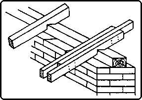
The cover straps shall be produced for re-proofing a building by
displacement of the rafter foot of a purlin roof.
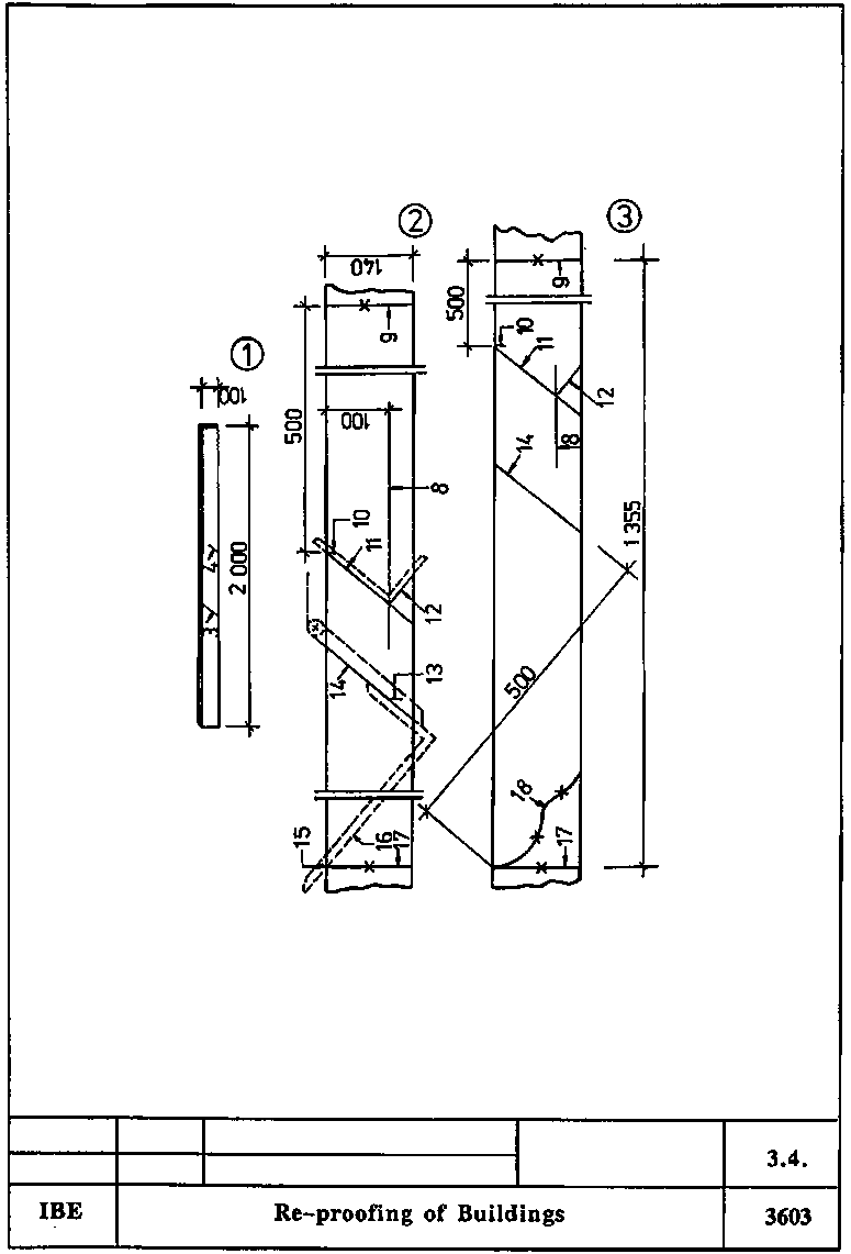
Figure
Dimensions
Cross section of roof rafter: 80/140 mm2
Thickness
of cover straps: 40 mm
Horizontal distance of eaves flashing: 500 mm
Hand tools and machines
Frame saw, hand plane, bevel protractor, band saw
Measuring and testing means
Folding rule, carpenter's steel square, water level
Auxiliary accessories
Straightedge 2000 mm long, pencil, abrasive paper, board of 140
mm width and 2000 mm length
Necessary previous knowledge
Reading of drawings, measuring and testing, plumbing
(perpendicularity), scribing, sawing, curving, planing, smoothing
(1) scribed straightedge
(2) board for template
(3) curve
of rafter foot
|
Sequence of operations |
Comments |
|
Steps 1 to 6 are to be carried out at the building! |
|
|
1. Check the scaffolding. |
Stability, bracing, covering of uprights, guard rail. |
|
2. Insert the straightedge between the roof boards and the
inferior purlin and press it against the roof rafter. |
Insert it approx. 1000 mm. Make sure that it contacts the roof
boards and the roof rafter. |
|
3. Transfer the front face of the outside wall onto the
straightedge by scribing the perpendicular line. |
Use a water level.
Check changing of water level. Mark
scribing perpendicular line with "PERPENDICULAR". |
|
4. Transfer front face of inferior purlin onto straightedge.
|
Mark only! |
|
5. Remove straightedge and insert it at several roof rafters to
check the scribed lines. |
|
|
6. Count the roof rafters. |
Is necessary for the number of cover straps required. |
|
All other steps are to be carried out in the workshop
|
|
|
7. Take perpendicular line from straightedge by means of bevel
protractor. |
Working direction from left to right!
Set bevel protractor
tongue exactly and firmly tighten the wing nut! |
|
8. Put board for template (approx. 2 m long) on work bench and
scribe on it square attachment timber. |
Scribe a thin line. |
|
9. Scribe angular line at right end of board and mark the
section to be cut off. |
Go only as far as necessary to produce a rectangular cut. |
|
10. Measure in and mark 500 mm from angular line to the left.
|
Measure on 8. |
|
11. Scribe perpendicular line through marking. |
Use bevel protractor. Perpendicular line is front face of
inferior purlin. |
|
12. Scribe surface of inferior purlin. |
Place square leg at perpendicular line so as to have point of
intersection with 8.! |
|
13. Take from straightedge, measure in on template and mark the
size up to front face of outside wall. |
Measure on 8.!
Mark only! |
|
14. Scribe perpendicular line through marking and mark with
"FW". |
"FW" means front face of outside wall. |
|
15. Mark horizontal distance of eaves flashing (500 mm) at long
leg of square. |
Apply only thin marking. |
|
16. Place tongue of bevel protractor at perpendicular line,
displace short leg of square at tongue so as to have point of intersection at
upper edge of template board! |
Place square and bevel protractor tongue exactly.
Do not
squeeze the tongue of the bevel protractor!
Apply only thin marking. |
|
17. Scribe template length and mark the section to be cut off.
|
Use a square. |
|
18. Profiling. |
Scribe the curve so that it can be easily sawn out with the band
saw! |
|
19. Saw out the template. |
Saw it out at exact angles. |
|
20. Smooth the template with abrasive paper. |
Use fine-grained abrasive paper.
No chamfers must be ground!
|
|
21. Measure length of cover straps and select timber for cover
straps in the timber yard. |
Number of cover straps has been counted on site. |
|
22. Transport the timber to the work bench and store it. |
Ensure freedom of movement. |
|
23. Put template successively on the timber for the cover straps
to be produced and scribe cover straps. |
Scribe cover straps on one side only.
Place upper edges of
template and cover strap flush with each other! |
|
24. Saw out the cover straps. |
Saw the curve exactly on the band saw!
Observe the safety
regulations for work on the band saw! |
|
25. Plane the visible sides of the cover strap foot. |
Use a hand plane.
Just smooth-plane, remove small chip. |
|
26. Smooth curve with abrasive paper. |
Use coarse-grained abrasive paper. |
|
27. Store cover straps for transportation. |
Store cover straps so that they cannot be damaged or get dirty.
|