| Formulae and Tables - Wood / textbooks for vocational training (GTZ, 122 p.) | |||||
| 10. Setting-up of Tools | |||||
| 10.1. Setting-up of Hand Tools | |||||
| 10.2. Setting-up of Machine Tools | |||||
|
| ||||||||||||||||||||||||
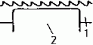
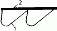
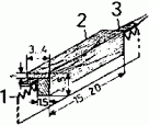
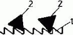
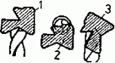
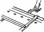
Setting-up of hand saws
|
Operation |
Aids/tools |
Remarks | |
|
cleaning of the saw blade |
petroleum thinner |
Remove glue residues, resin residues and similar | |
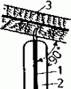
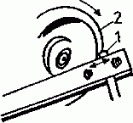
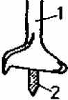
|
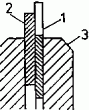
clamping of the saw blade |
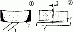
hand vice |
Clamp the saw blade horizontally, closely below the tooth gullet line. | |
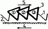
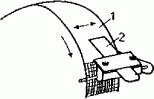
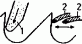
|
checking of the top line |
small glass plate or similar |
Differently long teeth lead to running-off centre of the saw; the saw blade is jolting during sawing. | |
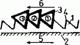
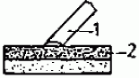
|
dressing of the saw blade |
clamped flat file |
File a uniform tooth line. | |
|
checking of the tooth form |
sheet-metal template for tooth - forms |
Find out which teeth are to be corrected. | |
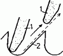
|
corrective filing of such teeth which deviate in form and
size |
saw file |
Hold the file horizontally and at right angles to the saw blade. | |
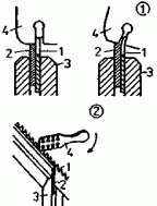
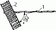
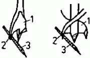
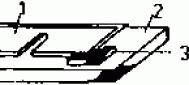
|
reclamping of the saw blade for saw setting with the saw
set |
hand vice and stop bar |
The teeth uniformly project 1/3 of their height beyond the stop bar. | |
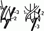
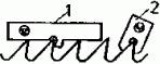
|
saw setting with the saw set |
saw set |
At first set every other tooth to one side and then - after
resetting the bar and the saw blade - the rest of the teeth uniformly to the
other side. | |
|
saw setting with saw set pliers |
saw set pliers |
Set the setting height and amount of deflection (setting width) on the saw set pliers. Mount without rule. | |
|
checking of the setting width |
saw setting gauge |
Move the saw-setting gauge with the recessed edge past the teeth in the blade plane. | |
|
correction of incorrectly set teeth |
saw set or saw set pliers |
Reset or further deflect the teeth concerned by the amount necessary. | |
|
equalizing |
flat file or hone |
Slightly “equalize” on the tooth line and at the tooth profile before sharpening to compensate the different resetting ability of the saw teeth. | |
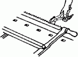
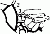
|
sharpening (filing) of the saw blade |
sharpening file |
Clamp the saw blade into the hand vice; tooth gullet line at the most 5 mm above the jaws. Hold the file exactly horizontally and at right angles to the saw blade; the same number of file strokes in every tooth space. File against the direction of the cut, move the file with uniform pressure. The tooth is sharp, when the tooth crest is not bright any more, but appears dull. File cutting face and flank uniformly. | |
Mistakes made when setting-up hand saws
|
Kinds of mistake |
Effects of the mistake |
|
missing or too small tooth set |
the saw is jamming or drifting |
|
too large tooth set |
unclean cut and bad guidance of the saw |
|
one-sided tooth set |
the saw deviates from the true course |
|
tooth set too deep (whole tooth height deflected) |
danger or cracking at the tooth gullet; insufficient stability of the saw blade |
|
filing into the direction of the cut |
the burr forming at the primary cutting edge acts in the direction of the flank and reduces the cutting effect |
|
canting on the sharpening file |
chip removal at the flank or cutting face too great; differences in the tooth height and wedge angle occur; cutting capacity is reduced, as only a part of the teeth is working; the saw is hacking |
|
deviation of the file position from the horizontal |
chamfering of the flank, change of the tooth height, reduction of the cutting effect |
|
file position not at right angles to the saw blade |
chamfering of the flank, change of the tooth height, reduction of the cutting effect |
Setting-up of plane irons and chisels
|
Operation representation |
Tools/aids |
Remarks |
|
cleaning of the plane iron and the flap or chisel |
petroleum or similar |
Remove resin and glue residues. |
|
Checking of observance of safety regulations | |
Use safety goggles or safety glass. Spacing between tool support and abrasive tool must be correct. Mounting flange diameter must be correct. Observe maximum permissible peripheral speed of the abrasive tool. Do test run of the abrasive tool. |
|
Checking of the cutting edge | |
Sharpen only when it is not possible any more to get a good cutting edge by dressing. |
|
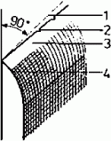
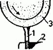
clamping of the plane iron |
plane iron and ripping chisel sharpening machine |
Firmly clamp the plane iron into the carriage, grind against the direction of rotation of the wheel. |
|
setting of the angle of support of the tool support |
plane iron and ripping chisel sharpening machine |
plane iron rest is sufficient; setting e is to be made in such a
way that the correct wedge angle (27°) is reached. |
|
reduction of the land width |
plane iron and ripping chisel sharpening machine |
This is necessary, if the wedge angle is too small. |
|
increase in the land with |
plane iron and ripping chisel sharpening machine |
This is necessary, if the wedge angle is too great. |
|
sharpening of the ripping chisel (straight flank) |
sharpening machine and cup wheel |
Clamping fixture is necessary. The straight flank produces a completely wedge-shaped cutting edge. It penetrates better into the wood. |
|
sharpening of turning tools (like ripping chisel with straight
edge) |
sharpening machine and cup wheel |
Clamping fixture is not absolutely necessary; tool support is sufficient, because due to the greather wedge angle of the tool cutting edge (see 7.4.) the angle of inclination of the tool to the sharpening wheel is considerably flatter than for the ripping chisel. |
|
honing of plane irons and ripping chisels |
hone |
Clamp the hone in position, firmly put on the land of the tool, hone with circular movements over the whole surface of the hone. Hone alternately the land and the minor surface of the tool, until the sharpening bun falls off by itself. |
|
Honing of turning tools |
hone |
Turning tools are honed by means of round, half-round or shaped
stones. |
|
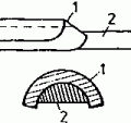
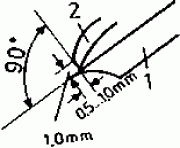
Setting-up of the plane iron flap |
sharpening file, hone |
File the front edge of the flap until it is at right angles to the central axis of the flap, has a width of 1 mm over the whole of its length, firmly rests on the minor surface of the tool after tightening the screw, has a uniform spacing to the cutting edge of 0.5... 1.0 mm; polish the bun edge brightly with a very fine hone. |
Setting-up of the scraper
|
Operation representation |
Tools/aids |
Remarks |
|
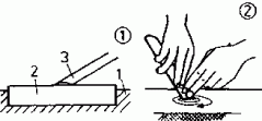
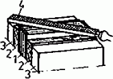
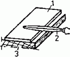
filing of the scraper |
vice, 2 hard wood blocks, flat finishing file |
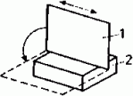
Clamp packs of several pieces between 2 hard wood blocks in the vice, align the edges in one plane, file the edges to be rectangularly even, longitudinal direction must be exactly straight, slightly round the comers. |
|
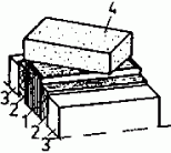
Honing of scrapers |
coarse hone |
Regrind the pack of filed scrapers by circular movement until the surface is completely smooth. |
|
|
fine-grain hone |
Hone the narrow and broad sides until the burr is completely removed and the edges are sharp-edged. |
|
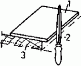
scraping off of the scraper |
scraper steel |
Place the scraper steel evenly on the scraper. Scrape off the surfaces under pressure from the centre outwards. |
|
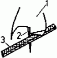
scraping of the cutting burr |
scraper steel |
Scrape the edge of the scraper with the scraper steel under
moderate pressure. This produces a cutting bun. |
|
resharpening of the scraper |
scraper steel |
A dull burr can be scraped off with the scraper steel and renewed several times, before filing becomes necessary again (round edges). |
Setting-up of drilling tools
|
Operation representation |
Tools/aids |
Remarks |
|
cleaning of drills |
petroleum or similar |
Remove impurities (resin residues etc.). |
|
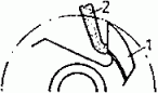
sharpening of the centre point |
sharpening file, hone |
File and hone the centre point uniformly from all sides until all file traces are removed. |
|
no filing of the infeed thread |
| |
|
sharpening of entering taps |
sharpening file, hone |
File the entering taps only from inside, then hone until all file traces are removed. |
|
sharpening of lips |
sharpening file, hone |
File lips from below, do not interrupt the connection between the lips and the infeed thread, hone carefully. |
|
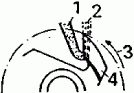
sharpening of twist drills with roof-shaped point |
plane iron and ripping chisel sharpening machine, grinding gauge |
Take the body of the drill with thumb and forefinger of the right hand. The left hand holds the drill at the shank and carries out an upward and downward movement of the drill between the horizontal and an imaginary line 15° below the horizontal. In doing so, continuously check by means of the grinding gauge the point angle, the shape of the cutting edges under the same angle, the concentricity of the point, the position of the chisel edge and the wedge angle. |
|
checking of sharpening | | |
Setting-up of circular saw blades and band saw blades
|
Operation Representation |
Tools/aids |
Remarks |
|
cleaning of the saw blade |
petroleum, thinner |
|
|
setting of the saw blades |
setting pliers, set gauge, setting dial gauge |
Use setting pliers. Because of its greater accuracy the setting dial gauge is more suitable than the set gauge for checking the setting width. |
|
clamping of the circular saw blade into the sharpening machine |
sharpening machine |
Saw blade bore hole must fit exactly on the centring taper; put grinding wheel head into highest position, set tooth height greater than necessary. |
|
setting of the saw blade thickness |
sharpening machine |
Middle of the saw blade exactly under the middle of the axis of the abrasive tool. |
|
setting of the rake angle |
sharpening machine |
In case of band saw blades set according to the scale of rake angles of the sharpening machine - choose it a little greater at first. |
|
setting of the saw pitch |
sharpening machine, measuring tape |
Measure the pitch at the saw blade and set it on the saw pitch scale of the machine. |
|
fine setting of the tooth feed |
sharpening machine |
Switch on the machine, set the tooth feed so that the abrasive tool coming down slightly attacks the cutting face. |
|
setting of the moment of shear |
sharpening machine |
The feed must start to act at the moment when the abrasive tool reaches the tooth gullet. |
|
sharpening |
sharpening machine, hone |
At least 4 sharpening passes are necessary; material removed per pass 0.05...0.1 mm; in the last pass only minimum metal removal (0.01... 0.03 mm); carefully remove the sharpening burr with a fine hone. |
|
setting of the tooth height |
sharpening machine |
Fine setting: |
|
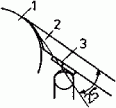
checking of the top line |
glass plate or tooth crest dial gauge |
Check band saw blades like hand saws (see par. 10.1.), check circular saw blades with tooth crest dial gauge. |
|
checking of cutting edge angles |
bevel steel square, plate template, wedge angle gauge or similar |
Check either with plate template as is done in the case of hand saws or with wedge or rake angle gauge or with bevel steel square. |
Mistakes made when sharpening the saw blades
|
Sharpening mistake |
Cause of mistake |
Effect of mistake |
Elimination of mistake | |
|
uneven flank |
feed is acting too early (flank becomes hollow) or too late (flank will get lugs) |
chip diasposal rendered more difficult, warming-up and drifting of the saw blades |
Set the moment of shear correctly. | |
|
tooth gullet radius too great |
saw pitch set to small |
low stability of the saw teeth, drifting of the saw blade |
Increase the travel of the feed pawl. | |
|
tooth gullet radius too small |
profile of the sharpening wheel rounded too little, wheel too thin |
drifting of the saw blade at higher feed |
Choose proper sharpening wheel, reduce the travel of the feed pawl. | |
|
tooth height too great or too small |
machine wrongly set |
changed tool geometry, shorter cutting life of the cutting edge, drifting of the saw blade |
Correct the fine setting of the tooth height. | |
|
tooth height not uniform |
axis of the sharpening wheel not exactly above the middle of the saw blade |
load on the saw teeth not uniform, quicker dulling, worse cutting quality |
Check the guidance of the saw blade and correct it. | |
|
discolouration of teeth crests |
too much material removed by grinding or peripheral speed of the sharpening wheel too high or sharpening wheel too hard |
loss of strength of the teeth crests, quicker dulling, drifting of the saw blade |
Correct the sharpening wheel’s action and the tooth feed, choose another sharpening wheel. | |
|
saw pitch not uniform |
tooth feed wrongly set, the sharpening wheel coming down too late attacks the cutting face too heavily |
load on the saw teeth not uniform, drifting of the saw blade, worse cutting quality |
Reset the sharpening wheel action on the cutting face. |
|
|
wedge angle altered |
tooth height setting too great (wedge angle becomes smaller) or too small (wedge angle becomes greater) |
altered tool geometry, worse cutting conditions, higher load on the saw teeth |
Correct the fine setting of the tooth height setting. |
|
|
remaining of a sharpening burr |
great abrasion, dull or excessively coarse-grained sharpening wheel |
quicker dulling of the cutting edges |
Make last sharpening pass with only little abrasion. | |
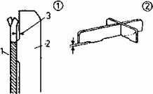
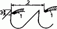
Setting-up of stripe irons
|
Operation |
Tools/aids |
Remarks |
|
cleaning of the stripe iron and the clamping surface |
solution |
Cleaning also serves for preventing grinding inaccuracies. |
|
clamping of stripe irons for sharpening |
sharpening machine |
Clamp the stripe irons on the grinding beam so that the cutting edges project about 2 mm beyond the grinding beam and the sharpening wheel can run a few centimetres beyond the end of the stripe iron. When clamping is made in a vice, clamp from the middle of the stripe iron outwards. |
|
infeed grinding |
sharpening machine |
Infeed the sharpening wheel according to the desired degree of keenness by 0.01...0.03 mm each. |
|
abrasive machining |
sharpening machine |
Grind in one pass; infeed according to the degree of dulling 0.1...0.4 mm. |
|
flat grinding |
sharpening machine |
Cup wheel is without tilt angle. |
|
finish grinding |
sharpening machine |
Grind with moderate pressure. In the last pass the sharpening wheel must come clear. Always grind against the land. |
|
hollow grinding |
sharpening machine |
Tilt the cup wheel by 2...3º in the running direction of the grinding wheel head; multiple honing is possible. |
|
honing |
sharpening machine |
Remove the grinding burr and fine traces of grinding. Hone only at the cutting face and always in longitudinal direction of the cutting edge. Hone must firmly be placed in position. |
Setting-up of milling cutters
|
Operation |
Tools/aids |
Remarks |
|
mounting of the cutter on the grinding arbor; centring |
sharpening machine |
Centring is made by means of centring rings. |
|
aligning of the cutting edges for sharpening |
sharpening machine |
Align always according to the shortest cutting edge which is determined by means of the dial gauge. |
|
grinding of the tool face |
sharpening machine |
Grind relief-turned cutters only at the tool face. |
|
radial infeeding |
sharpening machine |
Relief-turned cutters must be fed to the sharpening wheel radially, i.e. they must be turned around the axis during feeding. |
|
checking of the cutting rake |
sharpening machine, protractor |
In order to ensure always the same cutting rake, the chip removal over the whole tool face is not uniform (chip removal increasing towards the periphery). |
|
grinding of the flank |
sharpening machine |
Sharpen cutters with straight flank (see par. 9.4.) at the tool face and flank (with the exception of grooving and tonguing cutters which are sharpened only at the tool face). |
|
axial infeeding |
sharpening machine |
Sharpen cutters with straight flank mainly at the flank, in-feed axially. |
|
sharpening |
sharpening machine |
Grind all cutting edges uniformly. |
|
dressing of the sharpening wheel |
sharpening machine, silicon carbide stone |
In case of considerable dulling of the cutting edges dress the sharpening wheel once more before finish grinding. To do this, hold the silicon carbide stone by freehand at an angle of 10...15° against the rotating sharpening wheel. |
|
finish grinding |
sharpening machine |
In the final pass feed the sharpening wheel only slightly so that the sharpening burr can easily be removed. |
|
removing of the sharpening burr |
sharpening machine, hone |
Carefully hone the cutting edges to remove the sharpening burr. |
|
checking for true running |
sharpening machine dial gauge |
All cutting edges must lie on the same cutting circle (run-out £ 0.02 mm). |
|
regrinding |
sharpening machine |
Regrind projecting cutting edges individually to lie on the cutting circle. |
 |
 |