Back to Home
Page of CD3WD Project or Back to list of CD3WD Publications
 |  |  | Formulae and Tables - Wood / textbooks for vocational training (GTZ, 122 p.) |  |  | 9. Tools | |  | (introduction...) | | | 9.1. Tools for Circular Sawing Machines | | | 9.2. Tools for Table Band Sawing Machines | | | 9.3. Tools for Smooth and Thicknessing Millers | | | 9.4. Tools for Shaping Machines | | | 9.5. Tools for Slot Milling Machines | | | 9.6. Tools for Drilling Machines | | | 9.7. Tools for Sanding Machines | | | 9.8. Tools for Sharpening Machines |
|
Formulae and Tables - Wood / textbooks for vocational training (GTZ, 122 p.)
9. Tools
Machine tools are working tools which are held or fixed on
spindles and shafts or in chucks and
holders.
9.1. Tools for Circular Sawing Machines
Circular saw blades are toothed steel disks with a diameter of
80 to 800 mm, a hole having a diameter of 10...40 mm in the middle of the disk
and a disk thickness of 0.8...3.4 mm.
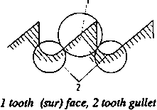
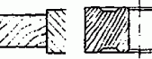
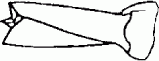
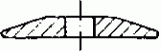
Figure 32 Tooth form
Construction of the tooth faces and tooth gullets
|
Number of cutting edges per tooth |
1 |
1 |
1 |
1 |
1 |
1 |
|
Representation |

|

|

|

|

|

|
|
Symbol Name |
N acute-angled tooth |
K gullet tooth |
p raven beak tooth |
A triangular tooth |
Y roof-shaped tooth |
S
- |
|
Number of cutting edges per tooth |
2 |
2 |
2 |
2 |
3 |
|
|
Representation |

|

|

|

|

|
|
|
Symbol |
X |
M |
Z |
B |
W |
|
|
Tooth gullets |
|
|
|
|
|
|
|
Representation |

|

|
|

|
|
|
|
Symbol |
C |
V |
|
U |
|
|
Tooth forms are designated by two letters, the first of which
designates the form of the tooth face, the second one the form of the tooth
gullet.
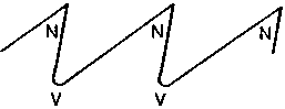
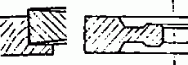
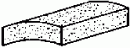
Figure 33 Designation
of the tooth form NV
Number of saw teeth and saw pitch
The saw pitch is the spacing between two successive primary
cutting edges, the saw pitch can always be divided by two.
Number of teeth (z) and saw pitch (t) of circular saw
blades
|
Diameter in mm |
KV teeth |
NV teeth
g >
0º |
NV teeth
g =
0° |
AV teeth |
|
z |
t |
z |
t |
z |
t |
z |
t |
|
in mm |
in mm |
in mm |
in mm |
|
80 |
|
|
64 |
4.2 |
|
|
|
|
|
100 |
|
|
64 |
5.2 |
|
|
|
|
|
125 |
|
|
80 |
4.9 |
|
|
|
|
|
160 |
|
|
80 |
6.3 |
|
|
|
|
|
200 |
|
|
80 |
7.8 |
80 |
7.8 |
|
|
|
250 |
|
|
80 |
10 |
80 |
10 |
|
|
|
300 |
56 |
17 |
80 |
12 |
80 |
12 |
72 |
13 |
|
350 |
56 |
20 |
64 |
17 |
64 |
17 |
72 |
15 |
|
400 |
56 |
22 |
64 |
20 |
64 |
20 |
72 |
18 |
|
450 |
56 |
25 |
64 |
22 |
64 |
22 |
72 |
20 |
|
500 |
56 |
28 |
64 |
25 |
64 |
25 |
72 |
22 |
|
550 |
56 |
31 |
64 |
27 |
64 |
27 |
72 |
24 |
|
600 |
56 |
34 |
64 |
30 |
64 |
30 |
72 |
26 |
|
650 |
56 |
36 |
64 |
32 |
64 |
32 |
72 |
28 |
|
700 |
56 |
39 |
64 |
35 |
64 |
35 |
72 |
31 |
|
750 |
56 |
42 |
64 |
37 |
64 |
37 |
72 |
33 |
|
800 |
56 |
45 |
64 |
40 |
64 |
40 |
72 |
35 |
|
Application |
for longitudinal cuts at normal load with manual feed |
for longitudinal cuts at normal load in hard and soft wood with
manual feed |
for cross cuts at normal load in hard and soft wood with manual
feed |
for cross cuts at normal load and with manual feed |
Recommended values for cutting edge angles
|
Cutting direction |
Application |
Tooth form |
Tool orthogonal rake g in ° |
Wedge angle b
in ° |
Plan angle c
in ° |
Setting width a in mm |
|
longitudinal cutting |
hard wood |
KV, PV |
22 |
46 |
87 |
0.35 |
|
|
NV |
18 |
40 |
87 |
0.35 |
|
softwood |
NV, KV |
28 |
40 |
87 |
0.45 |
|
dry |
PV |
|
|
|
|
|
softwood |
NV, KV |
28 |
40 |
87 |
0.45...0.40 |
|
damp |
PV |
|
|
|
|
|
cross cutting |
hard |
NV |
19...2 |
35...48 |
65...70 |
0.45 |
|
and softwood |
AV |
-10...-38 |
40...58 |
65...70 |
0.25 |
Information on labour safety
Use only unobjectionable saw blades. Do not exceed the speed
indicated on the tools. Replace dull, resinified tools. Check sharpened tools in
a test run for running accuracy. Do not change the tool geometry. Use suitable
tool containers for transporting circular saw blades.
Recommendations for maintenance
Clean the tools before using them. Protect the saw blades
against rust by means of an acid-free grease. Store circular saw blades by
hanging them up in the bore. In doing so, protect the cutting edges by layers of
cardboard or
similar.
9.2. Tools for Table Band Sawing Machines
Band saw blades for table band sawing machines are 10 to 40 mm
wide endless steel strips which are toothed on one side. They have a thickness
of 0.4 to 0.8 mm and a setting width of 1.0 to 1.3 mm.
Recommended values for band saw blades
|
Saw pitch t in mm |
Tooth height h in mm |
Setting width a in mm |
Tool orthogonal clearance a
in ° |
Wedge angle b in °
|
Tooth form |
Application |
|
12 |
4...5 |
0.4...0.5 |
20 |
45 |
NV |
for sawing soft wood |
|
10 |
3...4 |
0.3...0.4 |
30 |
55 |
NV |
for sawing hard wood |
|
8 |
3 |
0.3 |
30 |
55 |
NV |
for sawing laminated wood, sandwich, particle and fibre boards
|
Information on labour safety
Replace dull and resinified saw blades or clean and sharpen
them. Never use cracked or badly soldered saw blades. Do a 5 minute test run of
freshly soldered or welded saw blades before using them for the first time.
Soldering and welding points must not be thicker than the saw blade.
Recommendations for maintenance
Clean dirty saw blades with solvents and slightly grease them
against rust with acid-free grease. Keep saw blades in hanging position (teeth
towards the wall). When soldering cracked saw blades, cut the free ends
rectangularly, bevel them over 10 to 15 mm, file smoothly on both sides after
soldering and grind to the normal blade
cross-section.
9.3. Tools for Smooth and Thicknessing Millers
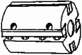
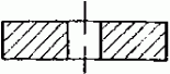
Smooth and thicknessing millers are equipped with blade shafts.
Blade shafts consist of a cylindrical body with locating spigot, they are
250...1600 mm long and their cutting circle diameter is 60...224 mm. The stripe
irons for tipping the blade shaft have cross-sections of 30 mm x 1.8 mm to 43 mm
x 2.2 mm and lengths of 200 mm to 810 mm.
Recommanded values for cutting-edge angles on stripe irons:
tool orthagonal rake g in º 30...40
tool orthagonal clearance a in ° 4...18
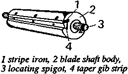
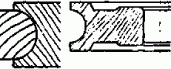
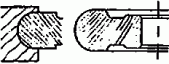
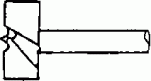
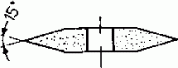
Figure 34 Blade shaft
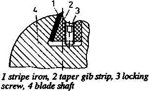
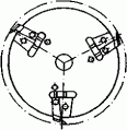
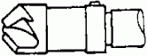
Figure 35 Mounting of
the strip irons on the blade shaft
Information on labour safety
For smooth milling machines only cylindrical blade shafts with
taper gib strips are permitted. The blades of smooth milling machines project
beyond the body of the blade shaft by 1.1 mm at the most. In case of smooth
milling machines make sure that the permissible weight difference of opposite
blades is kept. The cutting speed of 40 m/s must not be exceeded. Retighten the
fastening screws for the blades after a test run of 2 minutes. Tighten the
locking screws of the blade shafts alternately little by little starting from
the middle. The lips of the blade shafts must be close on the blades. The blades
must not be backed-up.
Recommendations for maintenance
Seatings and clamping surfaces for blades and clamping elements
must be absolutely clean when the blades are inserted. When replacing cutting
elements, make sure that the tool bore holes are clean. The tool geometry of the
blades must not be changed. Clean the tools from sticking dirt after using them,
protect bare parts against
rust
9.4. Tools for Shaping Machines
Tools for shaping machines may be solid or sectional. They have
diverse shapes and are provided with a bore hole for the cutter arbor.
Solid milling tools
As far as solid milling tools are concerned, body and cutting
edge are made of one and the same material and are integral. If the cutting edge
consists of a different material, it is permanently connected with material
closure with the body.
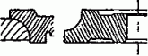
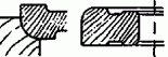
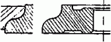
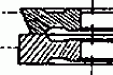
Arbor cutters
Form of the flank
|
Crown cutter |
Relief-turned cutter |
Relief-milled cutter or relief-ground cutter |
|

|

|

|
|
the flank is hollow-ground, so that symmetrical pairs of cutting
edges are produced |
the flank is curved (relief-turned) so that there will be no
friction between tool (flank) and workpiece |
the flank is straight (by relief milling or relief grinding)
|
|
for operations requiring a change of the direction of rotation
of the tool; it is disadvantageous that the unused cutting edge is rubbing
against the workpiece and gets dull as a result of this |
mainly for rebating and form milling tools; to maintain the
profile regrinding is made only at the tool face |
mainly for grooving cutters |
Kinds
|
Kind of cutter |
|
Dimensions in mm |
|
|
jointing cutter |
|
diameter |
63...80 |
|
|
working width |
28...63 |
|
rebating cutter |
|
diameter |
63...180 |
|
|
working width |
16...40 |
|
bevelling cutter |

|
diameter |
70...180 |
|
|
working width |
12...45 |
|
half astragal cutter |
|
diameter |
63...160 |
|
|
working width |
11 ...90 |
|
quarter astragal cutter |
|
diameter |
63...180 |
|
|
working width |
8...51 |
|
moulding cutter |
|
diameter |
63...140 |
|
|
working width |
2.5...25 |
|
half moulding cutter |
|
diameter |
63...180 |
|
|
working width |
8 ...51 |
|
cornice cutter |
|
diameter |
100...180 |
|
|
working width |
22...65 |
|
grooving cutter |
|
diameter |
80...125 |
|
|
working width |
4...14 |
|
cornice cutter with plate |

|
diameter |
80...200 |
|
|
working width |
12...42 |
Recommended values for cutting-edge angles on relief-turned
and relief-ground cutters
|
Application |
Tool orthogonal clearance a
in º |
Tool orthogonal wedge angle b in ° |
Tool orthogonal rake g in
° |
|
Softwood |
|
|
|
|
cutting direction A |
6...10 |
40...50 |
30...45 |
|
cutting direction B |
8...15 |
45...55 |
20...35 |
|
cutting direction C |
4...8 |
45...55 |
25...40 |
|
Hardwood |
|
|
|
|
cutting direction A |
8...12 |
45...55 |
25...35 |
|
cutting direction B |
8...12 |
55...65 |
15...25 |
|
cutting direction C |
6...10 |
55...60 |
20...30 |
|
chip board, uncompressed laminated wood |
5...10 |
55...60 |
20...25 |
|
hard fibre board, compressed laminated wood |
5...10 |
60...65 |
15...20 |
Sectional milling tools
Sectional milling tools consist of a body and cutting and
clamping elements. Only in combination they form a specific tool.
|
Tool |
Dimensions in mm |
Application |
|
cutter head |
diameter |
80...100 |
mainly for machining narrow surfaces, |
|
|
cutting-edge length |
80...125 |
depending on the construction of the cutter and the body also
for grooving, rebating and shaping |
|
cutter disk (slotted disk) |
diameter |
200...450 |
mostly equipped with two cutters for making |
|
|
cutting-edge length |
6... 20 |
of grooves, but especially for slotting (mortise and tenon
joints) |
Compound milling tools
Compound milling tools consist either of different single
cutters or of a set of single cutters of one the same kind. They are provided
for a specific work task. Any change of the form or dimension of the profile to
be made requires a change of the tool.
|
Tool |
Components |
Application |
|
dovetail cutting set
 |
grooving cutter and spacing collars |
for dovetailing diameter 100...200 mm |
|
cutter combination for the manufacture of windows
 |
one rebate cutter and one bevel cutter |
for milling of casement wood; today mostly cutter heads with
profile cutters are used for this purpose |
Recommended values for cutting-edge angles
|
Kind of tool |
Tool orthogonal rake g in
° |
Tool orthogonal clearance a
in ° |
|
cutter heads |
30...40 |
4...18 |
|
cutter disks |
37...45 |
15 |
Information on labour safety
Note maximum permissible tool speeds. Use collets only if they
have a collar and are inserted into the tool from both sides. Use upper bearings
depending on the tool size.
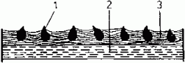
Figure 36 shows the use of upper bearings. Work without upper
bearing only within the hatched fields. Work with upper bearing only below the
curves I to IV. Never work above the curves. When the upper cutting edge of the
tool lies more than 100 mm above the table surface, work also with upper
bearing.
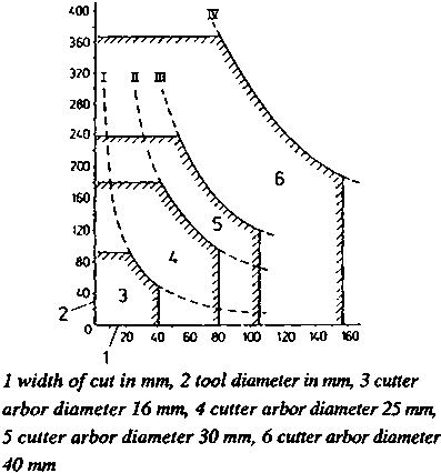
Figure 36 Use of upper
bearings
Tools with visible wear and damage are not permitted for use.
The damp nut must be held with all threads by the thread of the tool holder. It
must be designed as concentric nut with double-ended flattening for the wrench
jaw in case of cutter arbors. Note permissible tool dimensions. Locking screws
must be covered or recessed. Do not change the tool geometry.
See also hints on tools for smooth and thicknessing millers.
Recommendations for maintenance
Carefully clean the tool after use. Protect bare parts against
rust. Protect tool bore holes and tool shanks against any impurities. Keep the
tools in suitable cases ensuring protection of the cutting edges. See also hints
on tools for smooth and thicknessing
millers.
9.5. Tools for Slot Milling Machines
Tools for slot milling machines are shank cutters with one or
two cutting edges.
Shank cutters for slot milling machines
|
Tool |
Dimensions in mm |
Remarks |
|
slotting mill with one flute
 |
diameter |
4...16 |
single-edged with trough round shank |
|
cutting edge length |
10...18 |
|
|
slotting mill with two flutes
 |
diameter |
3...50 |
with through and with stepped round shank |
|
cutting edge length |
42...230 |
|
Recommended values for cutting-edge angles of slotting
mills
|
Tool |
Tool orthogonal wedge angle b in º |
Tool orthogonal rake g in
° |
|
Slotting mill |
70...79 |
11...20 |
Information on labour safety
Do not use any tools showing visible wear or damage. Mount the
tool safely. Locking screws must be covered or recessed. Do not change the tool
geometry. Work with guard bonnet over the drill chuck. Observe the specified
shank diameter of the tool.
Recommendations for maintenance
Keep the jaw chuck and tool shanks clean. Check the work
clamping device regularly for proper functioning. Lubricate according to the
lubrication chart. Regularly clean and grease the guide rails and lever
mechanism.
9.6. Tools for Drilling Machines
Tools for drilling machines are rod-shaped cutting tools with
front cutting edges and with shank for mounting in the drill chuck.
Kinds of drilling tools
|
Tool |
Dimensions |
in mm |
Application |
|
auger bit |
diameter |
6...40 |
especially for hand drilling units and deep holes, mostly with 1
or 2 taper tap(s) |
|

|
thread length |
78...1000 |
|
|
twist drill with roof-shaped point |
diameter |
3...8.3 |
for bore holes into hard wood and end-grained wood, mostly as
dowel hole drill |
|

|
thread length |
42...70 |
|
|
twist drill with centre point |
diameter |
4...50 |
for clean and accurate bore holes vertically to the wood fibre
|
|
|
thread length |
45...230 |
|
|
centre bit |
diameter |
8...50 |
with centre point and taper tap; for bore holes vertically to
the fibre direction |
|

|
length |
80...140 |
|
|
Forstner bit |
diameter |
8...40 |
for sinking dimensionally stable blind holes with even bore
bottom, e.g. knot bore holes |
|
|
length |
80...125 |
|
|
countersink |
diameter |
3...10 |
countersinks serve for making screw head counter sinks |
|
|
length |
90 |
|
Recommended values for cutting edge angles on drilling
tools
|
Kind of drill |
tool orthogonal clearance a
in º |
Wedge angle b in º
|
Drill point angle eB in ° |
|
auger drill |
15 |
25 |
180 |
|
twist drill with centre point |
12 |
45 |
90 |
|
twist drill with roof-shaped point |
15 |
45 |
100...125 or 180 |
|
centre drill |
20 |
25 |
180 |
|
Forstner bit |
20 |
30 |
180 |
Information on labour safety
When using drilling tools which are operated with a peripheral
speed > 6 m/s for the first time, do a test run of at least 1 minute. In
doing so, cover the area of danger. All locking bolts at the drill chuck must be
covered or recessed. The drill chuck must be firmly seated and well balanced.
The safety guards must be adjustable to different height and depth settings of
the drills.
Recommendations for maintenance
Take care to keep the tool shanks and drill chucks clean. After
use clean the tools carefully. Do not use any metal objects for cleaning the
tools. Store and transport the tools in such a manner that the cutting edges
cannot be
damaged.
9.7. Tools for Sanding Machines
Tools for sanding machines are flexible sanding tools. They are
used for wood and lacquer sanding. They are compound tools with geometrically
indeterminate cutting edges which consist of a flexible base body, a bonding
material and the abrasive material.
Construction of flexible sandig tools
|
Component |
Function |
|
base body |
The base body carries the abrasive material, has a high strength
and high flexibility. |
|
1 abrasive material, 2
base body, 3 bonding material
|
|
abrasive material |
Abrasive materials are the cutting edge bearing abrasives, they
perform the actual cutting operation. |
|
bonding material |
Bonding materials serve for attaching the abrasive materials to
the base body. |
Kinds of base bodies
|
Kind |
Stress level |
|
light papers made of soda pulp |
low |
|
compressed, sized papers made of soda pulp |
higher |
|
combination of paper and fabric |
high |
|
linen fabric |
very high |
|
combination of fabric and fibre |
very high |
|
fibre |
highest |
Abrasive material
|
Kind |
Symbol |
Application |
|
regular corundum |
NK |
for soft wood and rough plastic sanding |
|
semi-precious corundum |
HK |
for soft wood and rough lacquer sanding |
|
precious corundum |
EK |
for hard wood, lacquers, plastics |
|
silicon carbide |
SC |
for face veneer and polyester lacquers |
Grain sizes of flexible sanding tools
|
Grain group |
Designation |
Grain size of the main fraction in mm |
Grain group |
Designation |
Grain size of the main fraction in mm |
|
fine as dust |
F 3 |
3.0 ± 0.5 |
fine |
10 |
100...125 |
|
F 5 |
4.5 ± 0.8 |
|
12 |
125...160 |
|
F 7 |
6.5 ±1.0 |
|
16 |
160...200 |
|
F 9 |
9.5 ± 1.0 |
|
20 |
200...250 |
|
F 13 |
13.0 ± 1.8 |
medium fine |
25 |
250...315 |
|
F 17 |
17.5 ± 2.0 |
|
32 |
315...400 |
|
F 23 |
23.0 ± 2.5 |
|
40 |
400...500 |
|
F 29 |
29.5 ± 3.0 |
|
50 |
500...630 |
|
F 37 |
36.5 ± 1.5 |
coarse |
63 |
630...800 |
|
F 45 |
44.5 ± 2.0 |
|
80 |
800...1000 |
|
F 53 |
53.0 ± 3.0 |
|
100 |
1000...1250 |
|
very fine |
4 |
40...50 |
|
125 |
1250...1600 |
|
5 |
50...63 |
very coarse |
160 |
1600...2000 |
|
6 |
63...80 |
|
200 |
2000...2500 |
|
fine |
8 |
80...100 |
|
250 |
2500...3150 |
Spreading densities of flexible sanding tools
|
Designation |
Symbol |
Explanation |
Application |
|
closed spreading density |
cl |
There lies grain next to grain partly also one above the other
|
for very hard materials and small amounts to be removed. |
|
half-open spreading density |
ho |
small spacing between the grains, the spacing is smaller than
the grain diameter |
for hand sanding; when sanding is made by machine for hard wood,
plastics and lacquers |
|
open spreading density |
op |
The grain spacing is greater than the grain diameter |
especially for sanding soft and resin-containing wood |
Information on labour safety
Do not use any worn abrasive belts. Abrasive belts must not be
tarnished because of the danger of rupture. Keep the running direction printed
on.
Recommendations for maintenance
Carefully suck abrasive belts in the interest of prolonged
between-grind life. Store flexible sanding tools at a temperature of 16...22
°C and a relative air humidity of 50...55
%.
9.8. Tools for Sharpening Machines
Tools for sharpening machines are solid abrasive tools. They are
multi-cut chip-forming tools with geometrically indeterminate cutting edges,
consist of the abrasive body, the bonding material and have a porous structure.
|
Name |
Symbol |
Application |
|
normal corundum |
NK |
sharpening of tools made of tool steel |
|
semi-precious corundum |
HK |
same as normal corundum |
|
precious corundum |
EK |
sharpening of tools made of tool steel and high-speed steel
|
|
ruby corundum |
RK |
sharpening of tools made of tool steel, high-speed steel and
high-alloyed steel |
|
diamond |
D |
for dressing solid abrasive tools |
Bonding materials for solid abrasive tools
|
Kind of bonding |
|
Properties and application |
|
vitrified bond |
ceramic |
unlimited storage stability, sensitive to breakage, shock and
impact, sharp, most frequently used kind od bonding |
|
magnesite silicate |
limited storage stability, low strength, good self-sharpening,
for sharpening instruments |
|
organic bond |
rubber synthetic resin natural resin |
very elastic, hardly any danger of breakage, good cutting
capacity, high peripheral speed possible, well suitable for thin-walled abrasive
tools (abrasive cutting tools) |
Grain sizes of solid abrasive tools*)
*) See also under 9.7. Grain sizes of flexible
sanding tools
|
Grain group |
Grain size 1/100 mm |
Application |
|
coarse to medium |
80...50 |
grinding of shank materials |
|
medium |
40...32 |
rough grinding of tool cutting edges |
|
medium to fine |
25...16 |
finish grinding of tool cutting edges |
|
fine |
12...8 |
superfine grinding |
|
very fine |
4...3 |
for whetting and honing |
Hardness of solid abrasive tools (selection)
|
Designation |
Symbol |
Application |
|
very soft |
H |
blades for cutter heads, stripe irons |
|
soft |
i |
blades for cutter heads and cutter block spindles, milling
cutters |
|
Jot |
like under i, and drills |
|
K |
like under Jot |
|
medium |
L |
milling and drilling tools |
|
M |
milling and drilling tools, saw blades |
|
N |
like under M |
|
hard |
S |
dressing bodies for solid abrasive tools |
Selection of typical solid abrasive tools and their
application
|
Kind of tool |
Abrasive material |
Grain size |
Hardness |
Application |
|
|
NK |
20...32 |
M |
hand grinding; plane iron and ripping chisel sharpening machine
|
|
chamfered on both sides
 |
NK |
20...40 |
M |
saw sharpening machine |
|
round on both sides
 |
NK |
20...40 |
M |
saw sharpening machine |
|
chamfered on one side
 |
NK |
20...40 |
M |
saw sharpening machine |
|
cylindrical cup wheel
 |
EK |
63 |
H |
blade sharpening machine |
|
segmental tool
 |
RK/EK |
40...50 |
H |
blade sharpening machine |
|
tapered cup wheel
 |
EK |
25...32 |
Jot...N |
cutter sharpening machine |
|
dish wheel
 |
EK |
25...32 |
Jot...N |
cutter sharpening machine |
Information on labour safety
Carefully select the proper sharpening wheel. Do an obligatory
test run with every abrasive tool. Observe strictly the specified maximum
speeds. Use only well balanced abrasive tools.
Recommendations for maintenance
Keep solid abrasive tools in a hanging position. Mounting of the
abrasive tools must be done with greatest care. Use only abrasive tools provided
with all necessary specifications. Redress solid abrasive tools in time (to
ensure true
running).


