Back to Home
Page of CD3WD Project or Back to list of CD3WD Publications
 |  |  | Surface Water Drainage for Low-Income Communities (UNEP - WHO, 1991, 98 p.) |  |  | 2. Drainage options | |  | 2.1 The drainage hierarchy | | | 2.2 Factors affecting stormwater flows | | | 2.3 Problems of steep slopes | | | 2.4 Problems of flat areas | | | 2.5 Open or closed drains | | | 2.6 Channel design and construction | | | 2.7 Closed drains | | | 2.8 Construction | | | 2.9 “Do-it-yourself” drainage | | | 2.10 Selected reading |
|
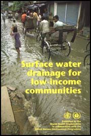
Surface Water Drainage for Low-Income Communities (UNEP - WHO, 1991, 98 p.)
2. Drainage options
2.1 The drainage hierarchy
The drainage problems of an individual neighbourhood are part of
a hierarchy of problems related to the drainage network of the whole city and
corresponding with the hierarchy of drains which compose it. These drains range
from the major canals or large sewers which collect water from large areas of
the city down to the small ditches or drainpipes that run along the roadside or
serve individual properties.
At the most basic position in the hierarchy is the receiving
water body into which the system discharges. This may be the sea, a lake or
a river. The water level in the receiving water body fixes the minimum level of
the drainage channels, because the pumping of storm-water is not feasible for
any but the wealthiest communities. Even if it were possible to afford pumps
large enough to handle the amounts of water involved, they would not be
practical because of the many difficulties of maintenance and the extent of the
damage that would result from malfunction or breakdown of the pumps. The water
level in the receiving water body comes very close to ground level in many flat
low-income areas, which means the drains cannot be made very deep.
Next in the hierarchy is the primary drainage system,
composed of main drains, sometimes called interceptor drains. These serve large
areas of a city or the city as a whole, and often follow the line of natural
drainage channels such as rivers or streams. The design, construction and
maintenance of a city's primary drains require extensive engineering skills and
a large financial base, and are well beyond the means of an individual
community. These drains are not considered here.
Finally there is the secondary drainage system, a network
of small drains within each neighbourhood. These are sometimes known as
micro-drainage or laterals, and each serves a small catchment area, ranging from
a single property to several blocks of houses. This publication deals
principally with the secondary level of the drainage system. At this level,
improvements can be made with modest investments, and low-cost solutions are
often
appropriate.
2.2 Factors affecting stormwater flows
Not all the water falling as rain needs to be removed by the
drainage system. Some of it will infiltrate into the ground, while some may
stand in puddles and other depressions and eventually evaporate. The proportion
that runs away over the ground surface and has to be carried in the drainage
system is known as the runoff coefficient. In practice, there is little chance
for evaporation during a rainstorm, so that the runoff coefficient to use when
calculating the size of the drains required is based on the infiltration
capacity of the ground. This depends mainly on soil conditions, the slope of the
terrain, and on land use:
Soil conditions. Water seeps more readily
into sandy soil than into clay or rocky ground.
Terrain. Water flows more rapidly down a steep slope,
leaving it less time to infiltrate than when it stands or moves slowly in a flat
area.
Land use. Vegetation traps much of the water and also
loosens the soil, thus making infiltration easier. Roofs and paved surfaces, on
the other hand, prevent infiltration.
Runoff coefficients are therefore higher in areas of clay soil
or rock, on steep slopes and in densely built-up areas with little vegetation.
As an example of this, the quantity of water to be drained from a high-density
housing area may be 5-6 times greater than it was when the area was undeveloped
and covered with vegetation.
The rate at which water enters the drainage system depends on
the runoff coefficient, but also on the rate of rainfall. Of course this can
vary, from a heavy downpour to a light shower, and it is hard to estimate the
maximum intensity of rainfall that will occur in a given year, because of the
unpredictability of the weather. However, by analysing past rainfall records, it
is possible to make an estimate of the probability of any particular rate
occurring. The more severe the rainstorm (i.e., the higher the rate of
rainfall), the lower the probability of its occurring.
This probability is usually expressed as a “return
period”. A rainstorm with a probability of 1 in 20 of happening in any
particular year is said to have a return period of 20 years, and is called a
20-year storm. This does not mean, of course, that it happens exactly every 20
years, but that on average it will happen that often - an average of five times
a century.
If a drainage system is designed for an unusually severe
rainstorm with a 100-year return period, it may never be fully used within its
lifetime. The money spent in constructing a system with such a large capacity
might have been better spent on building smaller drains in areas that have none.
Choosing the optimal return period for the design of an urban drainage system is
a difficult judgement based on weighing the risk of the drains overflowing, and
the damage this might cause, against the cost of building larger drains to
prevent it.
A return period of five years is widely used to design primary
drainage systems in tropical cities, but shorter periods (three years or less)
are more suitable for micro-drainage within residential areas, where an
occasional overflow is less likely to cause serious damage. In a low-income
area, where the value of property liable to damage is relatively small, and only
limited funds are available for drainage, the appropriate return period may be
shorter still. In Mombasa, for example, a one-year return period has been
adopted for all but the largest drains. In Calcutta some drains have been
designed for a return period of only two months. A few inches of flooding
several times each year may be a great improvement on waist-deep water for weeks
on end.
The damage that can be done to roads by stormwater is often the
major justification for drainage in low-income areas. On steep slopes, a single
heavy rainstorm that makes the drains overflow can cause enormous damage by
erosion, so that a longer return period may be justified than in flat areas.
Annex 2 gives further details of how to estimate stormwater
flows and use them to calculate the size of drains for design
purposes.
2.3 Problems of steep slopes
Sloping land easily suffers from erosion when the vegetation
cover is damaged and when intensive land use bares the soil. It is therefore
important to prevent water from rushing down in uncontrolled flows that may
undermine houses and turn paths and streets into impassable gulleys. As a rule
of thumb, slopes of more than 5% can be considered steep slopes.
On steep terrain, the only way to keep water in the soil is
through terracing so as to reduce the slope. Various methods exist and are used
to control erosion on agricultural land. However, these can be applied in an
urban area only if the neighbourhood has not already been fully built up.
When the water is concentrated in a natural or artificial line
of drainage running down a steep slope, it can flow at great speed and thus
cause considerable damage. Various methods can be used to lead the water down
gradually and in manageable quantities:
(a) Diverting the water horizontally by a
bank built along the contour or by turnout drains (Fig. 5), thus reducing the
speed of water flow and avoiding the accumulation of all the water from the
whole slope in a single drain.
(b) Leading the water in a controlled zigzag through
baffles built into the drain to slow down the flow (Fig. 6(a)).
(c) Building steps into the drain (Fig. 6(b)). The
area on to which the water falls from each step is built to resist the force of
the falling water. Step drains are practical if the slope exceeds 30%, but
otherwise they become too expensive.
(d) Checkwalls (Fig. 6(c)) are a less expensive
solution to the problem, and can be used in unlined drains. The water deposits
silt behind each checkwall, gradually building up a stepped drain. The
checkwalls should be set well into the ground on each side and beneath them, to
ensure that the water does not cut a way past them. In particular, the
foundation of each wall should not be higher than the crest of the next one
downstream.
Fig. 5. Turnout drains to divert
water from a steep slope
Fig. 6. Types of construction for
steep drains
Checkwalls can be built of various materials besides concrete or
masonry (Fig. 7). Piles of large stones help to dissipate the energy of the
water as it flows through the tortuous spaces between the stones. The stones
must be large enough to resist being carried downstream by the water.
In areas where rocks of sufficient size are not available,
smaller rocks may be tied together in a large bundle or bale known as a gabion.
A gabion is made by filling a large basket of galvanized wire mesh with stones,
to make a large rectangular bundle of about 0.5-1.0 m3. These can be
built up into a wall; however, it is advisable to fill them only after putting
them in position. Bamboo strips may be used as a substitute for wire, although
they will rot away in a few years. As the bamboo deteriorates, weak cement can
be applied sparingly to the exterior of the gabion, taking care not to block
completely the spaces between the rocks. When a gabion is newly placed, the
rocks have to settle down; a weak concrete would easily crack whereas wire and
bamboo are flexible.

Fig. 7. Types of checkwall or
dissipator
In areas with a moderate ground slope of about 4-10%, drainage
channels may be lined with concrete, masonry or vegetation to prevent scouring
of the channel bottom. Channel linings are discussed in section
2.6.
2.4 Problems of flat areas
In flat low-lying areas subject to flooding, a major problem
often results from the relatively high level of the receiving water body. This
limits the slope to which drains can be laid, so that water flows along them
quite slowly. Together with the difficulty of digging deep drainage channels
where the groundwater level is high, this means that drains have to be
relatively wide in order to have sufficient capacity.
Sometimes there is no alternative to using landfill to raise the
level of the ground in all or part of the neighbourhood. Landfill limited to the
streets will cause increased flooding of people's plots and houses, so that
adequate quantities should be provided, sufficiently close to people's houses
for them to cart it away and spread it on their premises. They should be helped
to judge how to place it by marks painted in advance on each house showing the
level to which the ground should be raised by the landfill.
The idea of people placing rubble and soil inside their houses
to raise the floor level may seem strange to some, but there are low-income
urban areas whose residents have been glad of up to 50 cm of landfill placed in
this way. Their houses will eventually need modification or rebuilding as a
result, but the impact of landfill can so transform an area that residents often
wish to build a new house more appropriate for the improved surroundings, once
they are convinced that it will be safe from flood damage.
The water level in the receiving water body often fluctuates,
owing to tidal effects or the flow of water into it from other catchment areas.
These variations in level can be analysed in terms of their return period when a
decision is made as to the depth of landfill required.
Alternatively, tidal variations in level can be turned to
advantage by installing a sluice gate at the outlet from the drainage system
which is opened at low tide and closed when the level rises. The need for
landfill can also be avoided by building a large embankment or dike along the
bank of a river liable to flood, or right around the residential area creating a
“polder” (Fig. 8). Of course, some installation such as a sluice gate
is needed to allow a way out for water drained from the area. However, no such
arrangement should be considered without very thorough study by an engineer and
a guarantee of reliable operation and maintenance. A dike that overflows or a
sluice gate that fails to function could do enormous damage.
Fig. 8. The polder system
Another difficulty in the drainage of flat areas is the
deposition of sediment in the drains, owing to the slow speed of flow of the
water. Where possible, drainage systems should be designed to produce a minimum
“self-cleansing” speed of flow, at least when the drains are running
full, so that water will carry the sediment along with it. In a drainage channel
with a rectangular cross-section, the water will flow slowly in a thin layer on
the bottom after light or moderate rain. Moreover, any irregularities in the
flat bottom will create puddles in which mosquitos can breed. Building a
drainage channel with sloping sides and a narrow bottom helps to maintain a
steady flow speed whatever the water level in the channel. A refinement of this
principle is to build a channel with a composite section (Fig. 9). The central
channel with a narrow bottom is to carry the flow in dry weather and moderate
rain, while the outer channel is for the occasional heavy flood flow. The outer
channel floor should preferably slope gently down to the central channel or
“cunette”.

Fig. 9. Cross-sections of typical
composite drainage channels
A self-cleansing speed of flow also requires a minimum slope,
which is greater for small drains than for large ones. Roughly speaking, a
channel 10-15 cm wide will need a minimum slope of about 1 % to achieve a
self-cleansing speed of flow. A channel twice the size needs roughly half the
slope. Such minimum slopes are not always achievable, though, as there may not
be a sufficient drop in level from the street to the receiving water body.
However well the system is designed, some sediment is bound to be deposited, so
that regular cleaning is essential to keep the drains
working.
2.5 Open or closed drains
Engineers and administrators often have a preference for closed
drains rather than open channels, probably because they are more accustomed to
them. Yet closed drains have several disadvantages:
(a) They cost more to build, because they
require deeper excavation, must withstand heavy loads on the street overhead,
and also require expensive additional works such as manholes and inlets.
(b) Construction defects, deterioration and accumulation
of debris or sediment are more difficult to monitor than in an open drain.
(c) The design, construction and maintenance of closed
drains require more sophisticated engineering techniques.
(d) Since closed drains are laid beneath the ground, a
smaller drop in level to the receiving water body is available to obtain a
sufficient minimum slope to ensure self-cleaning flow speeds.
(e) Mosquito breeding in closed drains is more difficult
to control.
(f) Slowly-moving sewage produces gases that can attack
cement and concrete in a closed drain if it is not well ventilated.
The main advantage of closed drains is that they do not take up
surface space. They also reduce the risk of children playing in or falling into
polluted water, and the possibility of vehicles damaging the drains or falling
into them. It is nevertheless a fact that open drainage channels are used and
maintained in good hygienic and aesthetic conditions in sophisticated cities
such as Amsterdam and Singapore. Closed drains should be built in low-income
tropical areas only after very careful consideration of the other options.
If open channels are built, careful thought should be given to
the question of access bridges across them to adjoining properties, for people
and vehicles. Without such provision, residents are likely to place stepping
stones in the drains, fill them with earth or obstruct them in other ways. The
worst option is a drainage system that is partly open and partly closed, so that
rubbish thrown into the open section blocks the closed sections, where it is
harder to remove. Water dammed up behind the blockage provides a shady stretch
of polluted standing water in which mosquitos can breed prolifically.
Some short covered sections are almost inevitable, however, at
road crossings and under access bridges. An iron grille should be placed at the
upstream end of each such section to keep out solids. If these are made as shown
in Fig. 10, then it will be easier to remove the accumulated debris by pulling
it up the bars with a rake.
The bottom level of a covered section should not be any lower
than the bottom of the channel downstream of it. Otherwise water will stand in
it, enabling mosquitos to breed, and it will also be likely to become blocked
with silt. If the pipe is of large diameter and if protecting it from damage by
traffic would entail burying it at a level lower than that of the channel
downstream, then an alternative is needed, such as a wide, shallow culvert
(e.g., a reinforced pipe) protected with a concrete slab cover.

Fig. 10. A type of grille which can
be cleaned easily with a rake
It is sometimes a conventional practice to build a small basin,
called a silt trap, at the entrance to a closed section. However, in most
low-income areas these fill very quickly with sand or rubbish, so that they are
of little use in practice. Because they are also breeding sites for mosquitos,
they should be
avoided.
2.6 Channel design and construction
The cheapest drains of all are unlined channels, which can be
cut along the roadside with a road grader. The sides of an unlined drain should
not slope by more than 1 in 2 to ensure that they will be stable. If the slope
along the drain is greater than about 1%, the drain may be damaged by scouring,
and some lining will usually be required to protect the channel bottom from the
fast-flowing water. For slopes of 1-5%, partial lining is likely to be
sufficient and will cost less than complete lining (Fig. 11). In a partially
lined drain, special protection is needed at the most vulnerable points, such as
culverts, drain junctions, sharp bends, and steep sections.
Another cheap measure, especially suitable for the upper part of
a partially lined channel, is to lay turf or sow grass, whose roots will help to
hold the soil in place. The most satisfactory grasses are those that spread
sideways and cover the surface of the soil. Their rapid growth can be encouraged
with fertilizer, by laying topsoil, and by building temporary checkwalls to
cause silt to be deposited.
For relatively gentle slopes, the lining does not have to be of
solid concrete or masonry. Compacted gravel or stone will be sufficient. Various
types of permanent and temporary lining are shown in Fig. 12. Drains with
vertical sides always need a lining to support the sides. As this type of
channel is used only when space is in short supply and when the drains have to
pass close to houses, the lining must be strong enough to protect adjacent house
foundations.
Lined drainage channels often fail because the lining does not
allow water to enter from the ground at either side. Either this causes water
pressure to build up and overturn the linings, or the water runs alongside the
drain, cutting a parallel channel. The solution is to provide weepholes, about
10 mm in diameter, in the lining at the sides. This can be done with short
lengths of pipe running horizontally through the masonry and embedded in the
mortar, spaced at intervals of not more than 1 m.
Fig. 11. Cross-sections of typical
unlined, partially lined and lined drains
In very narrow streets where heavy vehicles do not pass and
space is at a premium, the road itself may be designed to function as a drain
(Fig. 13). This is possible only if the slope is less than 5% and if the road
has a surface such as compacted gravel or stone to protect it from erosion.
Alternatively, drainage channels may be provided with removable covers (Fig.
13), which should have holes or notches in them to enable water to enter and
make it easier to remove them to clean the drain beneath. The latter approach
can also be used on very steep sections, with a series of prefabricated channel
elements laid as a stepped drain beneath a pedestrian stairway. Fig. 14 shows a
design of this kind used in the city of Salvador, Brazil.
Fig. 12. Types of drainage channel
lining
The smallest channels, less than 300 mm deep, do not need
weepholes, and can conveniently be lined with brick or with precast concrete
elements (Fig. 15). Elements should weigh less than 50 kg, so that they can be
carried and laid in place by two persons without machinery. Precast channels
should preferably be laid on a bed of compacted sand, 50 mm thick. A single
channel size can be adapted for larger flows by laying it deeper and building up
the sides with masonry.

Fig. 13. Combined drains and
pathways
Prefabricated elements have the advantage over masonry or in
situ concrete linings in that they can be laid relatively quickly. Masonry
drains take a long time to build, and concrete poured in place requires several
days to set. Meanwhile, local traffic is disrupted, and the fresh masonry or
concrete can be ruined by a sudden downpour of rain. If the drains are built in
the dry season to avoid an unexpected rainstorm, there may be a shortage of
water to cure the concrete in place. In a covered workshop, elements are
protected from the sun and rain, water for curing can be made available, and
quality control is easier and better than in conventional construction work.
Fig. 14. Combined footpath and
drain made of prefabricated elements, as used in Salvador,
Brazil
2.7 Closed drains
A common type of closed drain is constructed from prefabricated
sections of cement pipe, typically 1 m long and 50 mm in diameter. A tongue on
the end of each section fits into the next, ensuring that they are properly
aligned (Fig. 16(a)). If closed drains are used to convey sewage as well
as rainwater the drainage system is known as a combined sewer system, and
another kind of pipe connection is normally used to prevent the sewage from
leaking out and contaminating the groundwater (Fig. 16(b)).
Fig. 15. Cross-sections of three
types of small open drain
The trenches in which pipes are laid are normally dug at least
0.5 m wider than the pipe diameter, and deep enough for the top of the pipes to
be covered with at least 1 m of soil. Before the pipe is laid, a 50-mm thick bed
of sand is placed in the trench, compacted and carefully levelled to give an
even slope. The pipes are laid over the sand and a spirit level is placed on
each pipe to check the evenness of the slope. Then more sand is added and
compacted beneath and around each pipe until it is half buried. Finally the
excavated soil is replaced in layers 150 mm thick, each of which is compacted
carefully. The purpose of the sand bedding and the minimum depth of 1 m is to
protect the pipes from damage by heavy vehicles passing over them. In areas with
only very light vehicular traffic the sand bed can be omitted and the pipes laid
at shallower depth.
Fig. 16. Jointing of reinforced
concrete pipes
A closed drainage system must be provided with inlets for the
water to reach it from the road surface. These should be covered with a grille
to prevent leaves and other coarse solids from entering and blocking the system.
One inlet is usually provided every 30-50 m along the road, depending on the
slope and rainfall intensity. For the same reason that silt traps are not
recommended (see section 2.5 above), gully pots should not be provided at drain
inlets.
To facilitate cleaning and maintenance, manholes should be
provided at intervals of 120-150 m for pipes of more than 0.6 m in diameter, and
70-100 m for smaller pipes. They are also required wherever the pipes change in
diameter or direction, and at intersections. Further details on the design and
construction of closed drains are given in standard works on
sewerage.
2.8 Construction
Building a drainage system requires skilled supervision, but
many tasks can be done by the community. They include:
· excavation work
(digging);
· transport of soil, water, sand
and cement;
· compacting of soil or sand in
the drain foundation;
· prefabrication of
drain elements;
· watering and curing of
drain elements;
· transport and storage of
drain elements;
· accounting for drain
elements and guarding them;
· finishing and
planting of embankments;
· providing food for
volunteer workers.
Most of these tasks require little special skill and can be done
after an hour of instruction. The only task requiring real training is the
production of prefabricated drain elements.
The prefabrication of drain elements can easily be learnt by
semiskilled community members, for whom it may also prove to be an attractive
method of income generation. In many cities there is a ready market for
prefabricated elements of this type.
Two simple prefabrication methods are shown in Fig. 17. The
first was developed by the National Housing Authority of Thailand and offered to
small contractors. The other type of element was designed by the Roorkee
Research Centre in India and was intended to form the bottom part of shallow,
partially lined drains, although it can be used as a small drain on its own, as
shown in Fig. 15. The mould is covered by plastic sheeting or oiled newspapers
before the reinforcement and cement mortar are placed on it. A wooden board with
a semicircle cut out of it is moved along the channel to ensure that the mortar
has the correct thickness.
The purpose of the reinforcement is to prevent breakage during
transport of the elements, so that if they are not to be taken long distances
the chicken wire can be replaced with cheaper alternatives such as sisal or
coconut fibre. This makes the element very flexible while the mortar is still
wet, so that a third casting method can be used. The mortar is placed on a
plastic sheet while it lies on a flat surface. A rectangular wooden frame lying
on the sheet is used to give the layer of mortar the right length and width. The
vegetable fibres are spread on the mortar when it has been placed to half the
final thickness. When all the mortar is in place, a straightedge is used across
the frame to ensure that it has an even thickness - the depth of the wooden
frame. Finally, the frame is removed and the plastic sheet is lifted up by two
wooden battens previously fixed along the sides, and draped over a semicircular
concrete channel used as a concave mould.1
1 HILLMAN. E. Pre-fabricated
fibre-reinforced cement irrigation channels, Waterlines, 4 (4): 22-25
(1986).

Fig. 17. Methods of casting
prefabricated drainage channel elements
After two days of setting, the elements are removed from their
moulds and cured for 5-14 days so as to strengthen the concrete. As the
objective of curing is to prevent rapid evaporation of water from the surface,
curing is best done by placing the elements in a tank filled with water.
However, it is also acceptable to cover the elements with mats or fabric which
are then sprayed every evening with water, or otherwise kept wet, for at least
five days.
Construction should always start from the downstream end. This
keeps the working area dry and makes it easier to check the slope. Checking the
slope by eye is risky. Simply checking that water flows away down the newly-laid
drain will ensure that it slopes the right way, but in flat areas it may lead to
the drain being laid at too steep a slope, making it impossible to maintain an
adequate slope further upstream.
If surveying equipment is not available, a simple alternative is
a long plastic hose filled with water (Fig. 18). Make sure there are no bubbles
in it, and lift up both ends. The water level at each end of the hose will be
the same. If a slope of, for instance, 0.4% (0.004 m/m) is desired, this means a
difference in level along a 10-m length of drain of 0.004 × 10=0.04 m. If
the hose is held so as to keep the water level 1.00 m above the bottom of the
trench at the downstream end, the bottom should therefore be 0.96 m (1.00 -
0.04) beneath the water level at a point 10 m upstream. The same method can be
used to check the level of the drain elements when they are laid, using a piece
of string to check their horizontal alignment. A spirit level should be used to
check the slope of individual elements.

Fig. 18. Laying drains to an even
slope using a water hose level
It is not advisable to use such simple methods when laying
closed drains. A trained surveyor with proper surveying equipment is required.
The community's role in drainage construction can be
considerable (Fig. 19), but municipal authorities cannot rely on such community
participation to work smoothly in all cases, especially if unpaid work is
involved. If a contractor has been engaged for the construction work, he or she
may prefer to use his or her own staff so as to maintain control of the
construction schedule. If the contractor has to wait for the community to get
organized, the municipality may be charged for overheads and staff salaries
incurred during the delay. It is often preferable to write into the contract an
obligation to give priority to hiring local people and to training a local
maintenance team.
If the community is to participate in construction, substantial
effort must be devoted beforehand to mobilizing community members and organizing
their contribution, and their advice and agreement must be sought from the
beginning of the planning stage.
Fig. 19. Tasks in drainage
construction
A drainage scheme which is not accepted by the community is sure
to fail. Community participation is discussed in further detail in section
4.
2.9 “Do-it-yourself” drainage
Ideally, a community drainage scheme should be developed with a
local authority or other body which has the capacity to provide engineering
expertise. However, some communities may wish to undertake some improvements if
they prove unable to obtain such technical assistance, or while waiting for it
to materialize. This section suggests how they might do so, taking advantage of
the residents' ability to monitor the results of their work and make progressive
modifications in subsequent years.
The following initial steps (a)-(g) are
recommended to any group or individual wishing to plan a drainage scheme. No
specialized training is needed to carry them out. Engineers carrying out initial
studies may also find them useful as suggestions. For steps
(h)-(m), it is desirable to have the help of an engineer.
(a) Before you start your survey, it will be
wise to obtain a map of the area. Maps are usually obtainable from the city
planning department, the land registry or the national survey department. If no
up-to-date map is available, you can use aerial photographs, or a tracing made
from an original photograph. Quite suitable photographs for this purpose can be
taken with an ordinary camera from a small aeroplane, flying at a height of
about 600 m. At this low altitude, survey flights can be done under any
reasonable weather conditions. The shadows cast by clouds will not interfere
with interpretation of the photographs. As a last resort a sketch map can be
made; the section on plane table methods in a book on surveying will describe
how this can be done without sophisticated equipment.
The map should be of a convenient scale, preferably at least
1:5000. A scale of 1:1000 is best. A map that is of too small a scale can be
expanded with a pantograph, or by dividing it into squares and copying it on to
larger squares. You can then sketch in details, visiting the area to see if any
features are missing or need to be changed.
(b) Walk around the area. Ask the residents about the
probable causes of recent flooding or landslides. Residents may not have a
technical background, but they can usually identify the source of the water that
caused the problem. Long-standing residents may even be able to relate flood or
landslide problems to particular events in the past, especially to major civil
works carried out in the vicinity, such as the building of road or railway
embankments or cuttings, or the filling in of depressions.
(c) Try to establish the water levels reached during a
specific flood. Residents can describe the depth in terms of their anatomy
(ankles, knees, waist) or by pointing to parts of their fence or house. Marks
from a flood may still be visible on walls. Use a tape measure to express this
as a depth in centimetres, and write each measurement on your map of the area at
the appropriate point. Since water finds its own level, these measurements will
give you a good idea of the topography of the area; the greatest depths will be
in the lowest-lying areas.
(d) Note the natural direction of flow of wastewater from
houses, and of surface water from rainstorms. Mark existing lines of drainage on
the map, including both natural streams and man-made channels, noting problems
such as stretches of channel blocked by garbage, eroded sections, areas of
standing water, and landslides. Make a note of structures built along the
waterways which could obstruct drainage or prevent future widening.
(e) Note the discharge point and the water level in the
receiving stream, river or sea. Ask the residents about water level fluctuations
in the receiving water body, particularly the maximum water levels reached in
the last few years and, if possible, the dates on which they occurred. If the
receiving water body is a river, the water resources or hydrology department may
be able to help, particularly by giving you the dates and probable return
periods of major floods, which you can then compare with witnesses' accounts of
which areas were flooded on those occasions. If the receiving water is the sea,
the local port authority can provide tidal tables. The highest tides normally
occur in March/April and September/October.
(f) Prepare a sketch of the drainage improvements most
urgently needed, showing where expansion of existing channels is required, where
new drains will have to be dug, and where protection against erosion is to be
provided in steep areas. Drains should as far as possible follow existing or
planned road and path alignments. Nevertheless, some existing structures may
have to be moved, and these should be marked on the sketch map. Fig. 20 shows
the result of steps (a)-(f) in a particular community.
(g) Call a meeting of the residents and present the
proposed scheme to them for their suggestions and approval. Their intimate
knowledge of the area puts them in a good position to offer practical advice.
(h) Design the initial improvements. In the absence of
the information or technical assistance needed to make detailed design
calculations, it is best to start with unlined channels for flood control and
boulder checkwalls (or dissipators) to control erosion.
Unlined channels 0.3 m wide are a useful size for the small
branches along individual streets and alleys; if they prove to be too narrow,
they can be widened at a later date. A close look at existing lines of drainage,
including natural channels and especially constrictions which cause water to
back up behind them during storms, will give a good idea of the best size for
the major drains. If in doubt, channels 1 m wide would be a convenient size to
start with.
For steep areas, large boulders, preferably at least 30 cm in
diameter, can be used to build dissipator checkwalls held in place by wooden
stakes (see Fig. 7, page 18). If the boulders are washed away, it may be
possible to collect them and pack them in gabions. The spaces between the stones
should not be blocked with mortar, as this will only deflect the direction of
the water flow, causing erosion at another point. It is better for the water to
flow between the stones, dissipating its energy as it does so.
(i) Excavate the channels, starting from the downstream
end and working upstream. To drain flat areas, fix the downstream end of the
system at the lowest level possible without its becoming submerged by a typical
flood of the receiving water body, even if this means water may flow some
distance up the channels at high tide. The slope should be carefully controlled
using a water hose (see section 2.8). As a start, a rise of 0.2 m for every 100
m would be a reasonable minimum slope for a channel that is 1 m wide, and 0.5 m
for every 100 m in a channel 0.3 m wide. If the slope of the ground allows it, a
greater slope is better. If the slope is greater than 5 m in every 100 m, place
checkwalls as soon as possible after excavating the channel, one for every 1-m
drop in level.
(j) Once the channel has been excavated, visit after rain
has fallen and note which sections contain standing water. These are low points.
Either raise the bottom level by backfilling with gravel or soil, or deepen the
bottom downstream so that the water can flow away. Look also for early signs of
future erosion, such as water bypassing the checkwalls or running parallel to
the channel.
(k) Add a temporary lining if desired, such as the wood
or bamboo lining shown in Fig. 12, page 26. Temporary screens to hold back
rubbish can be installed across the smaller channels using wood or bamboo
stakes, with gaps of 20-50 mm between them. Allocate responsibilities for weekly
cleaning of each screen and organize a monthly work party to clear the major
channels.
(l) Monitor the system's functioning during at least one
wet season, noting areas of scouring, overflow, stagnant water, silt deposition,
or other problems. Water will tend to erode and deepen a channel if it is too
narrow and steep, and to deposit silt if it is too wide and the slope is
insufficient. Fig. 21 shows some of the changes that can occur in a typical
unlined channel, and how they can be used to diagnose the need for suitable
measures.
(m) After one or two years, the channel sizes and slopes
should be more or less established. The community may now decide to line the
channels, build permanent bar screens, road crossings, checkwalls,
etc.
Fig. 20. Sketch for planning a
drainage system
Fig. 21. Troubleshooting -
diagnosing problems in an unlined drainage
canal
2.10 Selected reading
CHATTERJEE, S. & BHUNIA, A. K. Drainage problem of
metropolitan Calcutta and its solution. Journal of the Institution of Civil
Engineers (India), 50 (10, part PH3): 83-92 (1970).
HILLMAN, F. Pre-fabricated fibre-reinforced cement irrigation
channels. Waterlines, 4 (4): 22-25 (1986).
MANOHARN, S. Application of ferrocement drainage flume in slum
upgrading. Journal of ferrocement, 12 (4): 373-383 (1982).
OKUN, D. A. & PONGHIS, G. Community wastewater collection
and disposal. Geneva, World Health Organization, 1975.
SHARMA, P. C. & KUMAR, A. Ferrocement channels for
small-scale irrigation. Appropriate technology, 9 (3): 7-8 (1982).
WATKINS, L. H. & FIDDES, D. Highway and urban hydrology
in the tropics. London, Pentech Press,
1984.


