9. The Technological Steps of Making Threaded Joints
The preparations for direct threaded joints differ from those
for indirect joints.
9.1. Direct Joints
Direct joints can be found mainly in parts or assemblies of
machines. Most threads are cut mechanically and the component parts are simply
joined by screwing. Make sure that the parts which are to be joined by screwing
coincide in their nominal thread diameters, pitch and sense.
Example:
Drill chuck on a machine spindle in a hand
drill.
Closing caps on containers.
Pipes may be directly joined by screwing as well. Most
connecting parts (pipe bells) and fittings (angles, bends) are manufactured
industrially and only an external thread needs to be cut on the pipe.
Task:
An unthreaded 1-inch (25-mm) steel pipe is to be
screwed into an elbow fitting heaving internal thread. A short external thread
is to be cut on the pipe.
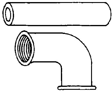
Figure 33. Pipe and elbow
fitting
Sequence of operation:
1. Prepare the die stock
- Mount the cutting dies with pipe
thread R 1-inch in the sequence of operations 1 to 4.
- Set the fine adjustment for the entering tap.
- Open the pilot.
2. Chuck the pipe, apply cutting fluid to the
deburred end of the pipe.
3. Place the die stock, pilot end first, on the pipe end, and
adjust the pilot.
4. Make an entering cut and rough cut over 19 mm length by
turning evenly in clockwise direction. Then loosen the clamping screw and break
the burr with a short jerk to the right.

Figure 34. Cutting
a pipe thread
5. Open the die stock and remove it. (Do not turn it to remove
it).
6. Set the fine adjustment for re-threading.
7. Place the die stock on the pipe and adjust the pilot.
8. Re-thread, then loosen the clamping screw and deburr the
pipe.
9. Open the stock and remove it from the pipe (Do not turn it to
remove it).
10. Clean the thread and apply some grease to it.
11. Screw the pipe into the elbow fitting until it stops. Use a
pipe wrench.

Figure 35. Making
a joint by screwing
Note:
- Where tight joints are to be made of pipes, apply
a packing of hemp tightly, starting from the front end of the pipe backwards.
Apply in right-hand direction if the thread is right-hand. Then apply acid-free
grease and screw into the internal thread, first by hand, then with a pipe
wrench.
- Where the pipe joint is to be made as a part of a permanent
pipe installation, use a pipe with long thread to ensure that the screwed joint
can be loosened even after a long time. Screw a pipe bell over the full length
of the thread. Use short thread on the pipe and press it flush on the long
thread. Then turn back the pipe bell and join both pipes without twisting either
of them.
9.2. Indirect Joints
Most threaded joints for fastening purposes are indirect joints.
When making the joint, make sure that the nominal diameters, pitches and senses
of rotation as well the material of bolts, screws and nuts coincide.
There are two main ways of making a threaded joint the indirect
way.
1. Bolt - component parts - nut
2. Bolt -
component parts - component part with female thread
Task:
Two steel parts are to be joined firmly by a hexagon
head bolt and a nut. The bolted joint will be exposed to dynamic stress, hence
it must be locked.

Figure 36. Joint made with a
bolt and a nut, locked with a spring ring
Sequence of operations:
1. Mark out the steel parts and punch a mark for the
bore hole centres.
2. Set up the steel parts for drilling. Drill holes together,
where possible. (The bore hole diameter should be slightly bigger than the
thread diameter).
3. Deburr both ends of the bore hole with a spotfacer.
4. Apply some grease to the bolt. Insert the bolt into the bore
hole and place a locking element (such as a spring ring) onto the end projecting
from the hole.
5. Screw on a nut for a few turns by hand, then tighten with an
open ended wrench.
Note:
- Use washers where the surface of the work is
unclean or smoothen the surface.
- Where the bore hole is provided when the part is supplied, use
a flat or pilot-type countersink to level the face which bears the bolt
head.
Task:
Three steel parts are to be joined firmly by a hexagon head
bolt. The receiving thread is to be in the last of the three component parts.
The bolted joint will be exposed to dynamic stress.
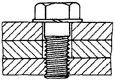
Figure 37. Joint made with a
bolt and a component part, locked with a spring ring
Sequence of operations:
1. Mark out all steel parts, punch a mark for the bore hole
centre.
2. Set up the steel parts for drilling, drill the holes
together, if possible. The bore hole diameter should be of the same dimension as
the minor diameter of the thread.
· Use the following formula to
calculate the drill diameter:
Where no values can be taken from handy tables, calculate
approximate values using the following formula:
3. Take the component parts apart and work them separately. Face
both sides of the hole with a 60° included angle countersink. The hole to
be faced is that in the last component part in the joint. The sink diameter is
to be the same as the thread diameter.
4. Bore an oversized hole in the two other component parts. The
dimension of the oversize depends on the nominal diameter of the bore:
5. Put the component parts are together, push the locking
element, such as a spring ring, onto the threaded bolt and apply some grease to
the threaded portion. Srew in by hand and then tighten with an open ended
wrench.
Five details of making a tapped hole for a
screw.
______________________________
______________________________
______________________________
- Where several component parts are screwed together
without a nut, the receiving thread must only be in the last part as seen from
the head of the screw. All in between parts have through holes.
- Heads of bolts and screws, when they are not to rise above the
surface of the workpiece, must be mounted flush. Cheese head screws are
countersunk with a piloted counterbore. Hat-headed screws are countersunk with a
90° included angle countersink.
- Locking devices are always assembled at the side with the
highest torque.
- Joints which consist of a bolt or screw and a nut always have
the highest torque on the nut. Hence, the head of the bolt or screw is held and
the nut is tightend.
- Always assemble a locking component at the nut end in joints
which consist of a bolt or screw and a nut.
- Where several nuts are tightened on a component part (for
example, the lid of a container), always start from the centre and proceed
outwardly, crosswise.
Where several component parts are to be joined by a screw, which
part must have a receiving
thread?
______________________________
______________________________
______________________________
How will you proceed in tightening several screws or bolts in a
lid of a
container?
______________________________
______________________________
______________________________


