Back to Home
Page of CD3WD Project or Back to list of CD3WD Publications
 |  |  | Lighting Installation - Basic vocational knowledge (Institut für Berufliche Entwicklung, 164 p.) |  |  | 6. Operating Components for Discharge Lamps | |  | 6.1. Ballast | | | 6.2. Starter Switches | | | 6.3. Ignition Sets | | | 6.4. Compensating Capacitors | | | 6.5. Intensity Control of Lamps |
|
Lighting Installation - Basic vocational knowledge (Institut für Berufliche Entwicklung, 164 p.)
6. Operating Components for Discharge Lamps
6.1. Ballast
With discharge lamps, the appropriately dimensioned ballast is
an important precondition for the achievement of the lamp life. If a ballast is
used which does not correspond to the respective lamp, the lamp parameters may
not be achieved and the service life of the lamp may be reduced.
The ballast must have sufficient temperature conditions for the
case of use they are meant for. These are printed on the ballast. For example:
105/55/140.
The meaning of these numbers is in succession: Winding limiting
temperature in degree centigrade, winding overtemperature in degree Kelvin in
normal and anomalous operation.
In normal operating conditions, ballasts in permanent operation
with the winding limiting temperature have a service life of 10 years. If the
ballasts are operated in anomalous conditions, at the limit of the then
occurring winding overtemperature, their service life expires after 20 days.
Towards the end of the service life, the ballasts fail due to break, interturn
short-circuits or body contact. With this, very high temperatures may occur on
the contact surfaces.
In the case of anomalous operation - for instance with
preheating of the lamp electrodes - and with 110 % of the rated voltage for
ballasts for lamps up to 400 W, the maximally occurring current is limited to
the 2.1-fold value of the rated lamp current with lamps of greater power to the
2.2-fold value of the rated lamp current.

Figure 37. Series reactor for
fluorescent lamps

Figure 38. Series reactor for
high-pressure mercury vapour lamps and halogen metal vapour lamps
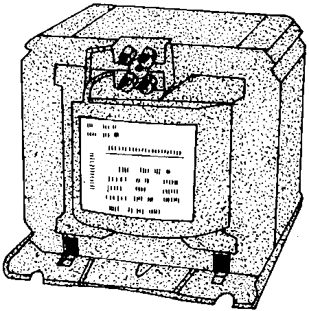
Figure 39. Series reactor for
high-pressure sodium vapour
lamps
6.2. Starter Switches
Starters consisting of the major components of glow starter and
capacitor are in important operating means of fluorescent lamps and recently in
special designs have also been used as starters for ignition sets.
The prolonged first make time for instance of the St l glow
starter for fluorescent lamps is within the range of 0.45 to 2 s; with most
starters it is 1 s on an average. The maximum voltage produced is more than 400
V, the test service life 6000 (number of switchings).
For tandem operation of fluorescent lamps of 20 W special
starter switches are required.
For starter ignition sets of high-pressure discharge lamps a
special glow starter without capacitor is used.

Figure 40. Starter for fluorescent
lamps
6.3. Ignition Sets
Halogen metal vapour lamps and high-pressure sodium vapour lamps
need ignition sets for starting the discharge. Two different types of sets are
available for the user - the starter ignition sets and the thyristor ignition
sets.
Starter ignition sets, in their essence, consist of a special
glow starter with a current-limiting capacitor and, perhaps, a protective
resistor connected in series, by which - including the inductivity of the
ballast - the required glitches from 1.5 to 2.5 kV are generated in the form of
irregular pulses.
Starter ignition sets are very economical as to the price; they
meet the requirements of the IP54 protective system and can be placed at a
distance from the lamp.
After ignition of the lamp there is no internal consumption. As
a wearing part the starter is considered as disadvantageous its replacement
requiring much maintenance work.
The thyristor ignition set is an electronic heterodyne ignition
set and consists of various semiconductor elements as well as of a pulse
transformer. The primary voltage of the pulse transformer is switched by a
thyristor controled by a diac.
The high-voltage pulses of approximately 4.5 kV and a natural
frequency of 100 kHz which develop at the secondary winding of this transformer
are superimposed on the network voltage near the maximum of the positive
half-wave. Ballast and secondary winding of the pulse transformer are connected
in series with the lamp, i.e. the lamp current flows over the secondary winding
which is designed for a continuous current load of 4.4. A. From this results the
power loss of the ignition set of maximally 4 W with the lamp burning. The high
tension is led out by an ignition wire which has to be connected with the
contact plate of the socket. The short ignition wire conditional on the set
requires the ignition set to be arranged near the socket of the lamp. After
having ignited the lamp the ignition set gives no further high-voltage pulses;
however, it continues to work if and when the lamp is defective or the lighting
outlet is unoccupied (continuous
ignition).
6.4. Compensating Capacitors
The current limitation by inductive ballasts with discharge
lamps causes a power factor of 0.4 to 0.7 according to the type of lamp; the
average is 0.5 approximately. The use of suitable capacitors enables an
improvement in the power factor - about 0.85. MP-compensating capacitors
(parallel capacitors) of 2 to 40 microfarad as well as motor and power
capacitors are used.
Furthermore, it is distinguished between single power-factor
compensation, group power-factor compensation in alternating current
installations and three-phase current installations and central power-factor
compensation. The last mentioned kind of compensation considers all inductive
consumers of the entire generating plant by a battery of capacitors based on an
automatic control by connecting and disconnecting individual capacitors
depending on the power factor measured. The capacity values of single
compensation are to be found in the respective tables.
Compensation capacitors are connected in parallel to the network
and must be disconnectable together with the entire installation. If a number of
single capacitors are used in order to achieve the total capacity, these must be
connected in
parallel.
6.5. Intensity Control of Lamps
With all-purpose lamps intensity control can easily be realized.
By a voltage dip of only 30 %, a luminous flux value of 1 % can
be achieved. This is done by using series resistors or - more economically - by
adjustable transformers. Modern electronical small devices on thyristor basis
are known as dimmers.
With fluorescent lamps, due to the falling characteristic of the
current-voltage-dependence and the required high reignition voltage, an
intensity control by reducing the voltage (amplitude control) is not possible.
Here, the principle of phase-shifting control is applied, i.e.
the lamp current and thus the luminous flux are changed in a wide range both
half-waves being used. The best control behaviour is shown by rod-shaped
fluorescent lamps of 40 W, which must be equipped with an ignition aid in the
form of an earthed starting strip or a closely spaced ignition grid. In addition
to the ballast, each lamp needs a heating transformer with two separate
secondary windings for preheating the lamp electrodes. The heating transformer,
for instance 220 V/2 x 6.3 V, 10 VA and the device for the phase-shifting
control must always be connected to the same external conductor. Because of the
low preheating voltage of about 6 V, attention has to be paid that the lamp
sockets give faultless contacts. In order to improve the quality of control, an
ohmic base load has to be connected to the load exit of the device according to
the instructions of the manufacturer (e.g. filament lamps 25 W).
To one light-controlling device, several lamps can be connected
according to the design of the device.
The regulating proportion that can be achieved is in the range
of 1:20 to 1:30; in favourable conditions a ratio of 1:100 is possible. Before
using fluorescent lamps for intensity control the entire lot of lamps of one
charge should be burnt in for approximately 20 hours.

Figure 41. Intensity control of
fluorescent lamps
1 control unit
2 series reactor
3 filament
transformer
4 lamp
5 ignition strip
To high-pressure mercury vapour lamps the above mentioned
methods cannot be applied, because a voltage dip of more than 15 % already leads
to the extinction of the lamp or to unstable operation.
Questions for repetition and knowledge tests
1. What are the distinguishing characteristics of ballasts of
fluorescent lamps compared with ballasts of high-pressure mercury vapour lamps?
2. Why are compensation capacitors required for discharge
lamps?


