Back to Home
Page of CD3WD Project or Back to list of CD3WD Publications
 |  |  | Electrical Machines - Basic vocational knowledge (Institut für Berufliche Entwicklung, 144 p.) |  |  | 6. Direct current machines | |  | 6.1. Constructional assembly | | | 6.2. Operating principles | | | 6.2.1. Power generation (direct current motor) | | | 6.2.2. Torque generation (direct current motor) | | | 6.2.3. Armature reaction (rotor reaction) | | | 6.2.4. Excitation | | | 6.2.5. Value relations | | | 6.3. Operational behaviour of direct current machines | | | 6.3.1. Direct current generators | | | 6.3.2. Direct current motors | | | 6.4. Circuit engineering and operational features of customary direct current generators | | | 6.4.1. Separate-excited direct current generator | | | 6.4.2. Direct current shunt generator | | | 6.5. Circuit engineering and operational features of customary direct current motors | | | 6.5.1. Direct current motor with permanent excitation | | | 6.5.2. Direct current series motor | | | 6.5.3. Direct current shunt motor |
|
Electrical Machines - Basic vocational knowledge (Institut für Berufliche Entwicklung, 144 p.)
6. Direct current machines
6.1. Constructional assembly
A direct current machine is a rotating electrical
machine which, according to circuitry, either utilises or releases
energy.
The direction of power conversion determines operation either as
direct current generator or motor. The direct current machine is an external
pole machine.
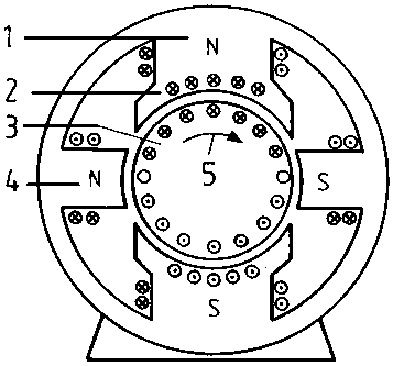
Figure 79 - Basic assembly of a
direct current motor
1 Main pole with exciter winding, 2 Compensation
winding, 3 Rotor with rotor winding, 4 Interpole with interpole winding, 5
Rotational direction during generator operation
The main poles with the direct current pole winding have been
arranged in the stator. These main poles set up the magnetic field (exciter
field) which, in the case of smaller machines, is also yielded through permanent
magnets. The rotable, pivoted rotor is made from a lamella sheet pack whose
grooves retain the winding.
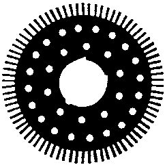
Figure 80 - Rotor-core lamination
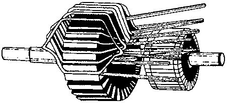
Figure 81 - Rotor with coil winding
The coil ends of the rotor winding have been extended to the
commutator lamella on which the brushes loop. In this way an electrical
connection is established between the direct current network and the rotor
winding (Cp. Figure 83). Interpoles whose windings are saturated with rotor
current have been interspersed in the field-free (neutral) zone of bigger
machines. In addition, under certain circumstances a capacitator winding has
been accommodated in the pole shoes of the main pole.
The overall assembly of a direct current machine is set out in
Figure 82.
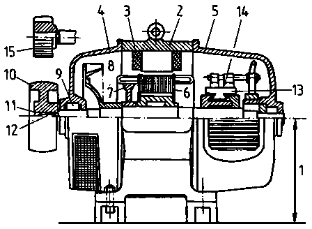
Figure 82 - Overall assembly of a
direct current machine
1 Rated height, 2 Stators, 3 Exciter winding, 4 End
shield of the A-side, 5 End shield of the B-side, 6 Dynamo sheets (armature), 7
Balance mass, 8 Ventilator, 9 Roller bearing, 10 Pulley, 11 Shaft end
(cylindrical), 12 Feather, 13 Commutator, 14 Brushes, 15
Gear
6.2. Operating principles
6.2.1. Power generation (direct current motor)
Initially (Cp. 4.1.1.) an alternating voltage is generated in
the rotor windings of every generator. This alternating voltage can, however, be
rectified so that current always passes through the external circuit in the same
direction (Cp. Figure 30). Rectification of the generated alternating voltages
takes place in the following manner: Instead of the two slip rings isolated from
one another in Figure 30, only one slip ring appears in Figure 83. This latter
slip ring has, however, been divided into two halves insulated from each other
(lamella) and is known as a commutator.
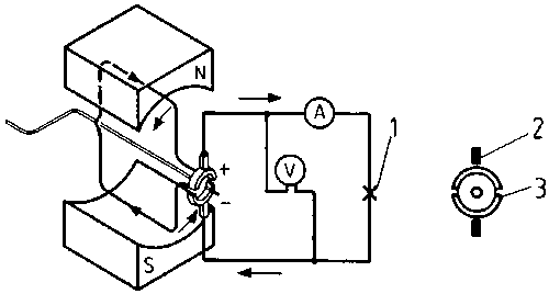
Figure 83 - Model of a direct
current generator
1 Bulb
2 Carbon brushes
3
Commutator
The beginning and end of the conductor loop (winding) have been
connected to the lamella. The two brushes face each other. They always run from
one lamella to another as the conductor loop passes through the neutral zone.
The induced voltage in the conductor loop is just zero at this moment and
changing its direction. Figure 84 shows the principle of mechanical
rectification.
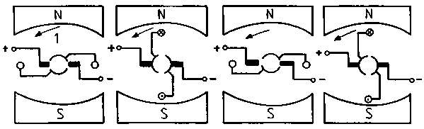
Figure 84 - Principle of mechanical
rectification
1, 2 Conductor loop, 3 Rotational direction, 4
Neutral zone
The commutator ensures that polarity of the carbon brushes
remains constant at all times. The course of the rectified voltage is shown in
Figure 85. We can perceive that the generated voltage still ranges between zero
and a top value whilst always evidencing the same direction.
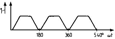
Figure 85 - Sequence of the
rectified voltage of a conductor loop
1 Voltage
Where a less pulsating voltage is required it is necessary to
increase the number of conductor loops whereby they should be spatially
positioned. The number of lamella must be increased for every additional
conductor loop. Figure 86 sets out the basic drawing of a direct current
generator with two conductor loops.
The commutator comprises four lamella. The generated voltage is
shown in Figure 87.
Figure 86 - Direct current generator
with two conductor loops resp. windings
1, 2 Conductor loop; 3, 4 Conductor
loop
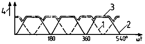
Figure 87 - Sequence of direct
current in a generator with two windings
1 Voltage in the conductor loop ½, 2 Voltage in
the conductor loop ¾, 3 Terminal voltage, 4 Voltage in volt
The resultant voltage no longer varies as much however it has
the disadvantage that the carbon brushes only tap off a voltage from the
conductor loops when they generate a peak voltage. The conductor loops are
ineffective at all other times. However, the two conductor loops add together
their voltages once they are series connected.
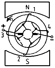
Figure 88 - Generator with
series-connected conductor loops
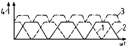
Figure 89 - Voltage sequence of a
generator in accordance with Figure 88 - Legend as for Figure 87
The voltage presented in Figure 89 also features an increased
voltage alongside an even one. Moreover, the direct voltage can be improved
still further by increasing the number of conductor loops. In practise coils
with several windings are employed instead of conductor loops. Operating current
IA flows when a consumer connects to the carbon brush
terminals.
6.2.2. Torque generation (direct current motor)
Section 2.3.2. indicates that a current saturated conductor loop
and a magnetic field are required in order to generate a torque. This is
attained by applying a voltage to the rotor winding as in Figure 83.
A rotational movement up to the neutral zone arises where direct
current flows into the rotor winding.
The forces are then still effective but do not constitute a
torque. The current direction in the conductor loop must be reversed in the
neutral zone in order to attain a further rotation. Current direction change in
the direct current machine is handled by the commutator which switches over the
current direction in the conductor loop after a semi-rotation. Thereby the
voltage attached to the carbon brushes is transformed in the conductor loop into
alternating voltage. Figure 90 depicts this process.
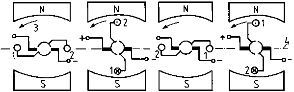
Figure 90 - Torque generation in a
direct current motor
1 Rotational direction
The following diagram emerges if one observes the torque within
the conductor loop depending on the rotational angle.
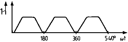
Figure 91 - Torque of a conductor
loop in dependence on the rotational angle
1 Torque
The torque ranges between zero and a peak value. A virtually
constant torque is attained by utilising a large number of conductor loops
(coils) which are distributed along the rotor circumference.
Conductor loop rotation in the exciter field similarly induces a
voltage in this field. This runs counter to the applied voltage and cuts back
operating
current.
6.2.3. Armature reaction (rotor reaction)
Mode of operation
The magnetic main field of the direct current machine runs
symmetrically from the north to the south pole (Figure 92 (1)) in the stator.
The current-saturated rotor winding generates a second magnetic field which runs
vertically (transverse) to the main field (Figure 92 (2)).
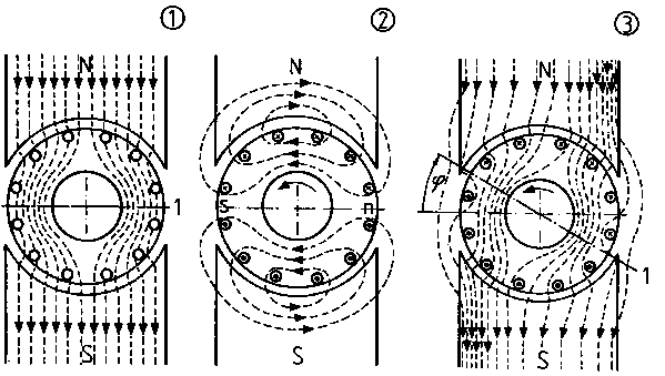
Figure 92 - Armature reaction
(1) Main field of the currentless rotor, (2)
Armature transverse field, (3) Resultant overall field
1 Neutral
zone
Despite rotor rotation the transverse field remains
motionless and its value only changes in proportion to the current intensity in
the rotor winding.
The armature transverse field superimposes itself with the main
field to a resulting field (Figure 92 (3)) whose neutral zone has been displaced
with regard to the main field.
The neutral zone is displaced by the armature
transverse field. Its rotation ensues in the generator in rotational direction
and, in the motor, contrary to the rotational direction of the
rotor.
A displacement of the neutral zone leads to brush sparking.
Furthermore, the armature reaction weakens the main field and this, in turn,
paves the way for a decrease in rotor-induced voltage.
Interpoles
The negative influence of the armature transverse field can be
overcome by superimposing a counter-directed magnetic field. So-called
interpoles (Cp. Figure 93) are established between the main poles.
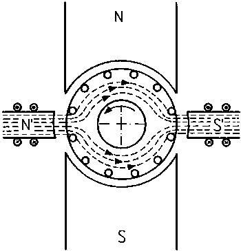
Figure 93 - Magnetic field of the
interpoles
1 Generator operation
2 Motor
operation
The interpole windings are so switched that their magnetic field
is counter-positioned to the armature transverse field. In this motor,
therefore, a principal north pole is followed by a north interpole in rotor
rotational sense.
The interpole shall generate a magnetic field
ouncterpositioned to the armature transverse field. The interpoles are in the
neutral zone. Interpole and rotor windings have been series
connected,
The armature transverse field can also be compensated by a
magnetic field which is generated by the so-called compensation
winding.
6.2.4. Excitation
Every rotating electrical machine requires an exciter field. The
exciter field of the direct current machine, generated by the main poles, is a
permanent magnetic field of constant value. We differentiate between various
exciter categories.
Permanent excitation
An exciter field is realised by means of permanent magnets. This
exciter category is mainly used for lower-power machines.
Separate excitation
The necessary voltage to generate an exciter field is attained
from a voltage source (e.g. accumulators) outside the machine. Natural
excitation is a particular excitation category.
In this case the necessary excitation voltage is provided by a
generator (exciter machine) which is coupled directly to the main machine.
Self-excitation
Because of remanance (residual magnetism), the main poles
evidence a weak exciter field. In accordance with U0 = c · F · n the rotation of the rotor winding induces only a
small rotor voltage in the exciter field. Rotor winding rotation however enables
a weak current to pass through the exciter winding. This current increases the
exciter field whereby a greater rotor voltage is induced. This is, moreover, a
continuous process leading to a fully fledged exciter field. This alternating
effect is termed “dynamoelectric principle”. One differentiates
between the following self-excitation categories:
Shunt excitation
The exciter winding has been parallel connected in the rotor
winding.
Series excitation
Both exciter and rotor winding have been positioned in series.
Compound excitation
Each main pole features two main types of exciter windings: a
shunt winding parallel to the rotor and a series winding in series with the
motor current
circuit.
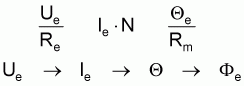
6.2.5. Value relations
A voltage U0 is always generated in the rotor circuit
irrespective of the type of direct current machine. The windings in the
operating field yield an ohmic resistor, the internal resistor R1. Both values
can feature in a duplicate circuit plan.
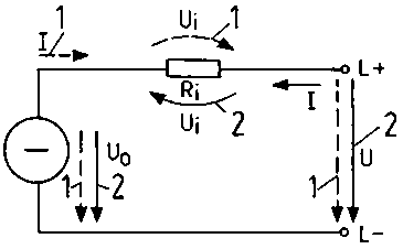
Figure 94 - Duplicate rotor circuit
The internal resistance of the rotor circuit stems from
|
R1 |
rotor winding resistance |
|
RW |
interpole winding resistance |
|
RK |
compensation winding resistance |
|
RB |
brush resistance and series excitation |
|
RR |
series winding resistance |
In accordance with the voltage law the duplicate circuit
establishes the relations between generator and motor operating voltages:
U0 = U + U1
U = U0 + U1
The natural direction change in switching over from generator to
motor operation must be heeded when drawing up the
equations.
6.3. Operational behaviour of direct current machines
6.3.1. Direct current generators
The induced voltage is determined by means of the equation
U0 = c · F · n
Thus we derive the value of U0
1. through the construction (C)
2. through the
exciter flow (F)
3. through the speed
(n).
The construction constant (C) which results from the
construction of the generator take in, for example, the number of pole pairs,
the number of rotor conductors and the interconnection of the rotor windings.
The exciter flow can be controlled by changing the exciter winding voltage. This
is possible by series connection of an alterable resistance to the exciter
winding. This is called resistance strain field actuator. Exciter voltage,
exciter current and excited flow are interlinked like this:
If U0 = f ((Fe)) is considered one can also investigate
U0 = f (Ie) as Fe is dependent on Ie. The
following diagram is forthcoming for a constant speed n (Figure 95): In the case
of a lesser exciter current the curve is almost linear. The curve flattens out
following increased pole iron saturation.
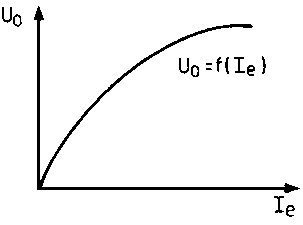
Figure 95 - U0 = f
(Ie); induction voltage as an exciter current
Figure 96 depicts the relationship between rotor speed and
induced voltage U0. Thus, the original voltage can also be attained
through the speed.
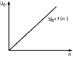
Figure 96 - U0 = f (n);
induction voltage as a speed function
The induced voltage of a direct current generator
can be controlled by altering the exciter current or the
speed.
6.3.2. Direct current motors
Starting behaviour
Direct starting
If the equation U = U0 + I Ri is adapted in line with
current magnitude, one derives an equation with

for working out the current value in the rotor circuit of the
motor. If one compares current intensity for switching on and actual operation,
we can determine the following:
During switching on current is calculated according to

There is thus more current because
1. the acceleration torque must be forthcoming
and
2. there is no back voltage U0.
As rotational movement continues a back voltage is induced
according to U0 = c · F · n whereby current
intensity declines. Current intensity decreases more and more as speed
increases. Then, as rated speed is attained, operational current is brought into
play. The very considerable inrush current leads to
1. a greater heating up of the winding
2. in
higher rated motors to operation of the fuses resp. the overcurrent trip
3.
to voltage fluctuations in the network.
Consequently, only motors with low rated power may be connected
to full mains voltage during switching on. Thus, motors operating on a mains
voltage of 220 V between both external conductors may not have a greater power
than 0.7 kW.
Direct switching on is only possible for low powered
motors.
Starters with series resistor
In the case of higher powered direct current motors the starting
currents are limited through a series resistor, the starter. The starter must,
moreover, be so dimensioned that peak starter current Isp does not
exceed 1.5 times the rotor nominal current (operating current intensity at rated
speed). Thus, the following equation applies:
Isp = 1.5 · In
This comprises several series connected resistors which can be
switched off as speed increases. The connecting terminals R, L and M should be
switched thus:
R to the rotor, L to the mains (lead) and M to the
shunt winding (magnetic field).
Starters are manufactured for the operating mode S2.
Example:
A direct current motor with a rated power of P = 10 kW and a
rated voltage of U = 220 V has an internal resistance Ri = 0.4. How
great are:
Starting peak current Isp
Starting
resistance Ra
and the relationship between switching on current
Ia max to rotor nominal current In?
Given:
U = 220 V
P = 10 kW
Ri = 0.4 W
Sought:
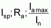
Solution P = U · I

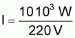
In » 45.5 A
Isp = 1.5 ·
In
Isp » 68 A

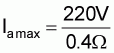
Ia max = 550 A
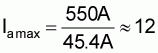
Ia max » 12
In
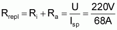
Rrepl » 3.24 W
Ra = Rrepl - R;
Ra = 2.84
Where a starter of at least 2.84 W is connected in series, the inrush peak current is
restricted to max 68 A. In the absence of a starter the inrush current would be
12 times greater than the rotor rated current.
Rating behaviour
Speed control
In practise prestipulated speeds are required for various
drives.
In production certain speeds must also be adhered to, moreover
such speeds shall also remain constant given loading variations.
Such drive problems can be solved by means of direct current
motors.
The equation for calculating the speed of a motor is derived
from U0 = C · F · n and U0
= U - 1 (Ri + Rv) through equalisation and subsequent
solution according to the speed.
We determine:
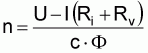
Rv is a series resistance which is series switched to
Ri.
Subsequently the speed can be set
1. by altering the applied mains voltage
2. by altering the series resistance of the rotor circuit and,
thereby, the voltage at terminals A1 and A2 of the machine and
3. by magnetic flow changes.
All these methods are used in practice.
Changing mains voltage.
Changing mains voltage is advantageous where a motor has an own
voltage source of differing values. Where direct current conductor mains are
available the voltage can be stepwise changed by means of a selector switch. The
influence of the mains voltage on the speed can be seen in Figure 97.
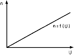
Figure 97 - n = f (U); dependence of
speed on mains voltage
Favourable and economical speed setting results from changing
the voltage by means of controlled rectifiers (thyratrons or thyristors). There
are virtually no losses with these rectifiers. Power dependency becomes
irrelevant as rotor resistance does not change during this procedure.
Changing the series resistance of the rotor circuit
Where rotor circuit resistance is increased through a series
resistance, speed subsequently decreases.
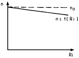
Figure 98 - n = f (Ri);
speed dependence on internal resistance
However, due to the considerable rotor current, this speed
control leads to marked power losses. Where this procedure shall serve for speed
control, the servo unit is dimensioned for permanent S1 operation. Such a unit
is called a speed control starter if it is simultaneously suitable for starting.
This control leads to a power drop.
Changing the magnetic flow
The magnetic flow decreases when a speed field controller is
switched on to the field winding. The speed increases in the diminished exciter
field. In practise speed field starters are constructed permitting a speed
increase of up to 200 per cent of the rated speed. The arising losses are
relatively low, consequently this control unit is quite economical. Figure 99
depicts the dependence of speed on exciter flow.
Figure 99 - n = f (F); speed dependence on exciter flow
Rotational direction control
The rotation direction depends on the current direction in the
rotor and the direction of the exciter field. This is determined by the
left-hand rule.
A rotational change of direction can therefore be attained
1. by current directional change in the rotor
and
2. by pole changing the exciter field.
In practice the current directional change in the rotor is
mainly used. However, the exciter field is repoled in more powerful machines
(Leonard converters) as, otherwise, the switching contacts to handle the
extremely great rotor currents become too
big.
6.4. Circuit engineering and operational features of customary direct current generators
6.4.1. Separate-excited direct current generator
Circuitry
The separately excited direct current motor is a
direct current generator whose exciter winding is fed by a separate voltage
source.
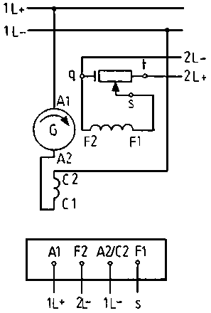
Figure 100 - Circuitry and terminal
board of a separately excited direct current generator
Voltage behaviour
The induced rotor current is virtually load independent given
constant rotor speed and exciter flow. Conversely, terminal voltage U drops
slightly as load increases. The graphical presentation of the function U = f (I)
is a declining straight.
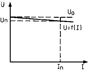
Figure 101 - Voltage curve of a
separately excited direct current generator
The separately excited generator cannot be short-circuited.
Voltage - control
By means of the voltage field actuator the exciter flow can be
altered from minimum to saturation value. Consequently, the induced voltage can
be varied within considerable limits.
Application
Due to the considerable voltage setting range, the separately
excited generator is utilised where very different voltages are required, for
instance in
converters.
6.4.2. Direct current shunt generator
Circuitry
The direct current shunt generator is a direct
current generator in which the exciter winding is switched parallel to the rotor
winding.
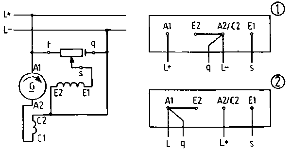
Figure 102 - Circuitry and terminal
board of a direct current shunt generator
(1) Clockwise, (2) Anti-clockwise
Voltage behaviour
The dependence of terminal voltage U on load current I can be
deduced from the curve in Figure 103. Terminal voltage declines as load current
increases. If the generator is, in addition, loaded over and beyond the rated
current, the terminal voltage declines sharply. Only minimal voltage is induced
where the rated current increases threefold. Consequently, the required current
power need no longer be provided. Terminal voltage is zero during
short-circuiting.
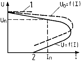
Figure 103 - Voltage curve of a
direct current shunt generator
1 U0 in no-load operation
2 Short
circuit current
The shunt generator is short-circuit-proof.
Voltage control
An alteration of the strain field actuator of the exciter
current and, thus, also of the exciter flow serves to ensure constant voltage
given greater load current.
Application
The direct current shunt generator is used as exciter generator
in three-phase generators for ensuring power supplied on ships and
planes.
6.5. Circuit engineering and operational features of customary direct current motors
6.5.1. Direct current motor with permanent excitation
Circuitry
The permanently excited direct current motor is a
small machine in which the exciter field is established through permanent
magnets.
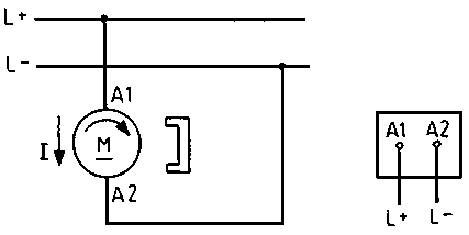
Figure 104 - Circuitry and terminal
board of a direct current motor with permanent excitation
Dependence of current take-up on the torque (load)
As the curve I = f (M) indicates in Figure 105, current take-up
is directly proportional to the torque because of the constant exciter flow.
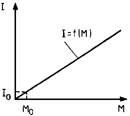
Figure 105 - I = f (M); Current
take-up dependence on torque
Dependence of speed on the torque (load)
Direct proportionality exists between speed and torque in
speed-load behaviour.
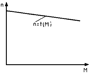
Figure 106 - n = f (M); Speed
dependence on torque
Speed control
Speed control ensues by changing the applied voltage.
Application
Direct current motors with permanent excitation are used mainly
for power ratings up to 500 W. Such motors find application in the toy industry,
household appliances, measurement and control
technology.
6.5.2. Direct current series motor
Circuitry
The direct current series motor is a direct current
motor whose exciter windings (D1, D2) have been series-switched to the rotor
winding.
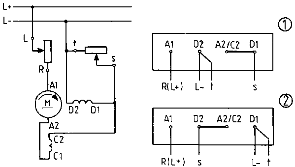
Figure 107 - Circuitry and terminal
board of a direct current series motor
1 Clockwise, 2 Anti-clockwise
Dependence of current take-up on the torque (load)
Current take-up by the motor depends on the load. As curve I = f
(M) indicates, during idling the motor only takes up minimal current. Current
take-up increases through greater load. Thereby, however, the increase in
current intensity is greater than the load growth.
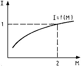
Figure 108 - I = f (M); Dependence
of current take-up of a direct current series motor on torque
1 Rated current, 2 Rated torque
Dependence of speed on the torque (load)
The speed-torque curve (Figure 109) shows that the speed depends
to a considerable extent on the load. Whilst idling speed assumes greater
values. Given reduction the motor may “race” under certain
circumstances.
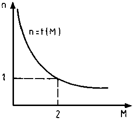
Figure 109 - n = f (M); Speed
dependence on the torque of a direct current series motor
1 Rated speed, 2 Rated torque
The considerable centrifugal power which then arises can destroy
the motor. Therefore the motor must be securely attached to the drive machine.
Speed declines markedly as the load increases. The direct current series motor
develops a considerable initial torque during starting. It can, therefore, also
start given excessive load.
Speed control
Speed can be controlled by
- a series resistor
- a strain field actuator
parallel to the exciter winding and by
- changing mains voltage.
Application
Direct current series motors are used where considerable speed
ranges and excessive torques are in evidence and “racing” is not
possible (e.g. for driving electric railways, cranes,
escalators).
6.5.3. Direct current shunt motor
The direct current shunt motor is a direct current
motor whose exciter windings (E1, E2) have been series-switched to the rotor
winding.
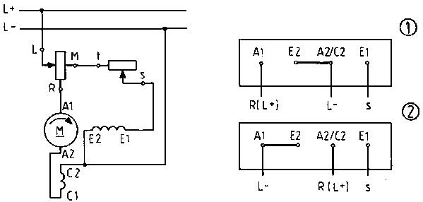
Figure 110 - Circuitry and terminal
board of a direct current shunt motor
(1) Clockwise, (2) Anti-clockwise
Dependence of current take-up on the torque (load)
Current take-up is made up of rotor current IL and
exciter current Ie : I = IL + Ie. The curve I =
f (M) (Figure 111) shows that exciter current flows as M = 0. Current take-up
increases as load increases. Very considerable current flows during overloading.
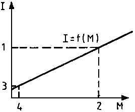
Figure 111 - I = f (M); Current
take-up dependence on the torque of a direct current shunt motor
1 Rated current, 2 Rated torque, 3 Idling current
(exciter current), 4 Idling torque
Dependence of speed on the torque (load)
Speed behaviour is characterised through minimal linear speed
reduction as load increases.
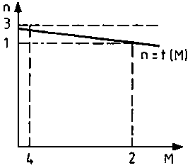
Figure 112 - n = f (M); Speed
dependence on the torque of a direct current shunt motor
1 Rated speed, 2 Rated torque, 3 Idling speed, 4
Idling torque
The unloaded motor runs at an idling speed of N0 and
the rated speed of nn is less than 10 per cent.
The speed change between the idling speed n0 and the
rated speed of nn is less than 10 per cent.
Speed control
Sound speed control is possible by altering the exciter flow
with the aid of the strain field actuator and varying the applied mains voltage.
Application
The direct current shunt motor is used as a drive for machine
tools and automation equipment because of its virtually constant speed.
Questions for repetition and control
1. Describe the construction and mode of operation of a direct
current generator.
2. Differentiate between the different types of direct current
machines.
3. How can the speed of a direct current shunt motor be changed?
4. Explain why a starter is required to start up a direct
current motor?
5. How can one alter the rotational direction of a
motor?


