| Compressed Earth Blocks - Volume II. Manual of design and construction (GTZ, 1995, 148 p.) | ||||
| Masonry principles | ||||
| (introduction...) | ||||
| Mortar | ||||
| Bonding patterns | ||||
| Coursing | ||||
|
| ||||||||||||||||||||||||||||||
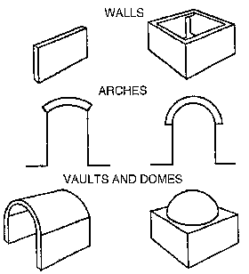
A compressed earth block masonry structure consists of small building elements placed one on top of the other following a particular bonding pattern and bound together with mortar.
The earth blocks therefore form a building system - whether it be a wall or a partition, a post or a pillar, an arch, a vault or a dome - which has compressive strength. This characteristic of compressive strength is indeed essential as, by contrast, masonry structures using small elements have very little tensile strength.
The good strength and good stability of a masonry structure using small elements is dependent on the interaction of several factors:
- the quality of the block itself,
- the quality of the masonry (i.e. the interaction between the block, the bonding pattern and the mortar),
- the form of the building system, which should be suited to the compressive forces exerted,
- the quality of detailing of the building system, notably
ensuring good protection against water and
humidity,
- the quality of execution of the work.
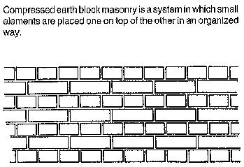
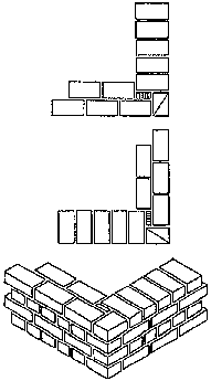
Fig. 29: What is CEB masonry
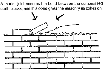
Fig. 30: What part does mortar play
in CEB masonry
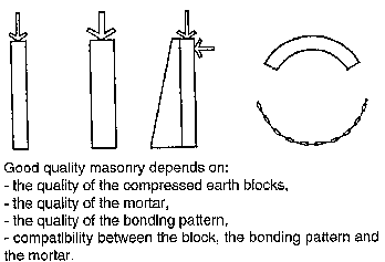
Good compressive strength implies
The shape must suit the masonry structure
Fig. 31: The quality of CEB masonry
Possible uses of compressed earth
block masonry
Compressed earth block masonry can be used for any kind of structure required by compressive forces:
Fig. 32: Wich building systems to use with CEBs?
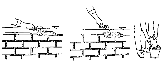
FIGURE (FIG.33;34;35)
Fig. 33: Laying the right amount of mortar.
Fig. 34:
Spreading the mortar out evenly.
Fig. 35: Pre-soaking stabilized blocks.
Definition
A mortar is a mixture of aggregates (sand and fine gravel) with a binding agent (generally cement or lime), to which water is added in previously determined proportions. Used in a plastic state, mortar ensures good mechanical bonding between the masonry elements making up a wall, a pillar, or other building systems.
Role
In compressed earth block construction, as in construction using other masonry elements (such as stones, fired bricks, sand-cement blocks), mortar plays a threefold role:
- It bonds the masonry elements together in all directions (vertical and horizontal joints).
- It allows forces to be transmitted between the elements and notably vertical forces (i.e. the weight of the elements themselves, or applied forces).
- It enables these forces to be distributed across the whole surface of the masonry elements.
- It compensates for any defects in horizontality in the execution of the masonry work.
Properties and characteristics
When freshly mixed, mortar should be easily "worked". Apart from having a suitable consistency, it should display good cohesion, as well as the capacity to retain water against the suction of the masonry elements on which it is applied.
Apart from its consistency, mortar used for compressed earth block construction should:
- Be able to change shape.
- Allow good permeability to humidity.
- Have mechanical performances which are compatible with that of the compressed earth blocks.
Composition
The composition of the mortar should in each case take account of the actual requirements of the masonry structure.
A good mortar should have good mechanical strength and should have the same compressive strength and resistance to erosion as the compressed earth blocks.
Too low a strength mortar carries the risk of erosion, water infiltration and the deterioration of the compressed earth blocks. Erosion and cracking of the mortar, in addition to tensile forces, results in a risk of rupture.
Too high a strength mortar carries the risk of water stagnating on parts of the visible mortar matrix standing proud of the surface which in turn causes the erosion of the blocks; this can result in the blocks cracking and in lowering their strength.
The texture of a good mortar is generally more sandy than that of compressed earth blocks, with a maximum particle diameter of 2 to 5 mm. Stabilized mortar must always be used with stabilized compressed earth blocks. In this event, the proportion of cement or lime used should be increased by a factor of 1.5 or 2 to achieve the same strength as the earth blocks.
It could be possible to use a non-stabilized earth mortar if one is sure that the walls which are to be built with this mortar are well sheltered from exposure to rain or to water in general. But even so, it will still be necessary to ensure that the non-stabilized mortar has the same compressive strength and resistance to erosion as the earth blocks.
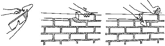
FIGURE (FIG.36;37;38)
Fig. 36: Spreading mortar well on the to be bounded.
Fig. 37:
Laying the block with a sliding motion.
Fig. 38: Pushing the block firmly
into place without hiting it.
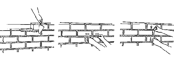
FIGURE (FIG.39;40;41)
Fig. 39: Removing excess mortar.
Fig. 40: Smooting the
horizontal joints.
Fig. 41: Smooting the vertical joints.
Disadvantages
Mortars have certain weaknesses:
- they shrink as they dry out,
- they can be chemically
unstable,
- they can present a lower strength surface at the point of contact
between the mortar and the block in a solid state.
The main disadvantage is due to the hardening through drying out with a significant risk of shrinkage occurring. This shrinkage can cause the masonry to settle. This danger can be avoided by not making joints too wide, by using a fairly sandy mortar, or by wedging the joint apart by adding small stones.
Good practice
The mixing water of the mortar should be clean (i.e. clear and non-acidic). The surface to which it is to be applied should be prepared and clean.
The bonding of the blocks should be correct in both directions of the bonding pattern, using vertical and horizontal joints. Vertical joints should be well filled. Care should be taken to prevent the mortar drying out too quickly (e.g. sprinkling the wall in hot countries) and in general to avoid dramatic changes in temperature (special care must be taken in regions where the diurnal temperature range is particularly great.)
The width of the mortar joints, both horizontal and vertical, should be even and a maximum of 1 to 1.5 cm.
For stabilized compressed earth blocks, blocks should be pre-soaked, and the surface on which they are to be placed should also be moistened. The block should be "spread" with the right quantities of mortar on the sides to be bonded.
Once the block has been laid, it should be pushed firmly into place, but above all it should never be tapped or hit as this could destroy the adherence between the block and the mortar.
The joints should be smoothed as soon as the blocks have been laid, either using a jointer, or a piece of wet plastic tubing, wood or bamboo.
Fig. 43: Finished appearance of joints. Joints can be finished in three ways, giving different appearances:
1 - flush with the wall
2 - slightly hollowed out (concave)
and rounded
3 - hollowed out (concave) and chamfered
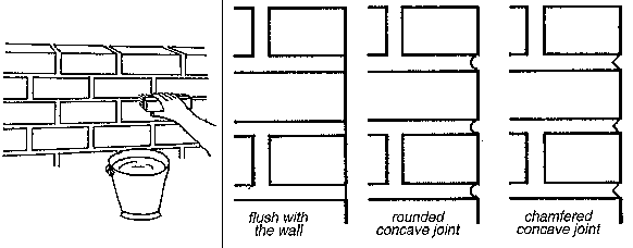
FIGURE (FIG.42;43)
Fig. 42: Brushing for the final finish.
Fig. 43: There are three possible types of joint.
The term "bonding pattern" refers to the way in which compressed earth blocks are arranged, assembled and therefore bonded together in all directions of a masonry structure (horizontally and vertically, and in the thickness of the wall). The bonding pattern determines the position of each earth block from one course to another and notably prevents vertical joints occurring one immediately above the other, which would entail the risk of cracks spreading through the structure. Bonding patterns play an essential part in ensuring the cohesion, the stability and the strength of masonry structures built from small elements bonded together with mortar.
Deciding which bonding pattern to use should be done before the masonry work begins will depend on five interrelated factors which should be considered together:
1 - the type of structure (wall, partition, pillar, other),
2
- the size of the structure,
3 - the dimensions of the compressed earth
blocks,
4 - the skill of the masons (appropriate level of complexity),
5 -
the aesthetic effect required of the finished appearance of the external faces
of the structure.
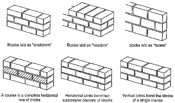
TERMINOLOGY FOR TYPES OF BONDING
PATTERN (FIG.44)
Fig. 44: Basic terminology of ways of laying blocks to form bonding patterns using small masonry elements.
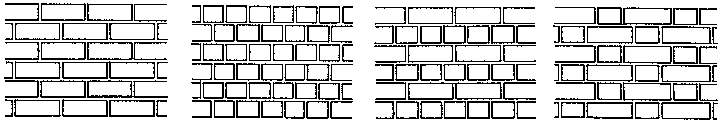
Fig. 45: Fundamental rules of
bonding patterns to avoid superimposed vertical joints. (A;B;C;D)
A;B) A good bonding pattern has no superimposed vertical joints, i.e. no vertical joint immediately above another between the bonding pattern therefore consists of courses laid alternately and shifted along, using one or two types of bonding pattern.
C;D) Generally, the minimum distance between two blocks in two successive courses should be equal to a quarter of the logest side of the block (its length).
To build simple earth block masonry structures, such as walls, the most common bonding patterns require the use of half and three-quarter dimension blocks, as well as of full blocks Fig. 46 shows a half block being used at the end of a wall, the width of which is equal to a half block. Fig. 47 shows a three-quarter block being used at the end of a wall, the width of which is equal to a full block.
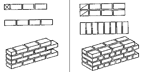
FIGURE (FIG.46;47)
Fig. 46: "Half-block" thickness wall.
Fig. 47: One-block
thickness wall.
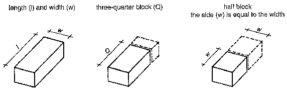
TERMS OF BLOCK DIMENSIONS
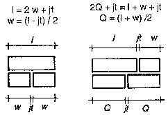
THICKNESS OF THE MORTAR JOINT (jt)
(FIG.48)
Fig. 48: Terms and rules for block dimensions using simple bonding patterns.
DIMENSIONS OF COMMON BLOCK AND
DERIVATES (FIG.49)
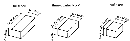
Fig. 49: The most common dimensions of compressed earth blocks and its derivates ( common half and three quarter blocks).
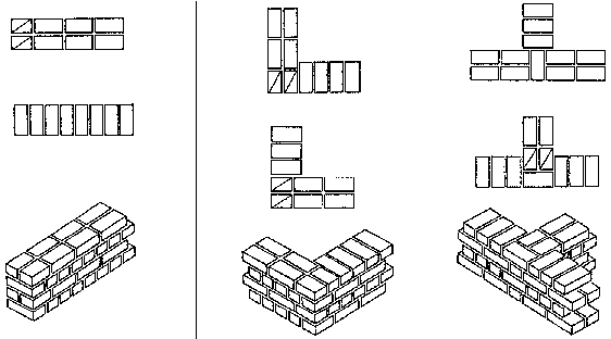
A few examples of bonding patterns for walls the width of which is equal to a half-block. These bonding patterns use full' half and three-quarter blocks.
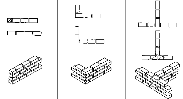
FIGURE(FIG.50;51;52)
Fig. 50: half block used at the end of alternate courses and
continuous wall.
Fig. 51: Corner of wall using full block
Fig. 52:
"T"-shaped bonding pattern using three-quater blocks
FIGURE(FIG.53)
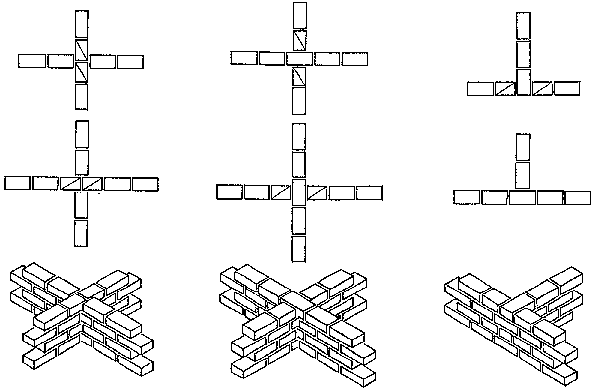
Fig. 53: "X"-shaped and "T"-shaped bonding patterns using three-quarter blocks.
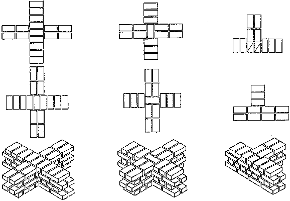
A few examples of bonding patterns for walls the width of which is equal to a full block. These bonding patterns use full, half and three-quarter blocks.
FIGURE(FIG.54;55)
Fig. 54: Three-quarter block alternate courses and continuous
wall.
Fig. 55: "L" and "T"-shaped bonding patterns using three-quarter blocks
FIGURE(FIG.56)
Fig. 56: "X" -shaped and bonding patterns using full blocks and "T"-shaped bonding patterns using three-quarter blocks.
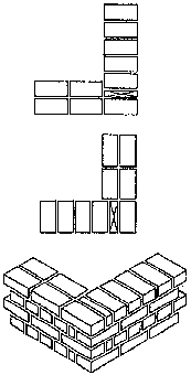
Header bonding patterns for wall systems where the width of the wall is equal to a full block often require the use of a three-quarter block. Here it is shown being used at the end of a continuous wall and at the junction of two walls in an "L" or "T" shape.

FIGURE(FIG.57)
Fig. 57: A few examples of header bonding patterns for walls one block thick.
More sophisticated header and stretcher bonding patterns, still for walls the width of which is equal to a full block, can combine the use of full blocks cut across their width, full blocks cut lengthways, and quarter blocks. These solutions should, however, be avoided as they can weaken the structure of the corner.
In this example (Fig. 58 a) of a corner using headers and stretchers, the two three-quarter blocks are replaced by a full block and a half-block cut lengthways.
FIGURE(FIG.58a)
Fig. 58 a: Corner bonded using headers and stretchers without three-quarter blocks.
In this example (Fig 58 b) of a corner using headers and stretchers, a three-quarter block is combined with the remaining 1/4 block which would otherwise be wasted when the full block is cut.
FIGURE(FIG.58b)
Fig. 58 b: Using a quarter of a block with a three quarter block.
Bonding patterns for small section posts or pillars (30 × 30 cm or 30 × 45 cm) generally require full blocks and use a rotating pattern or reversed symmetrical patterns.
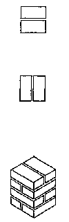
Fig. 59 a: Simple bonding pattern
for a 30 cm pillar.
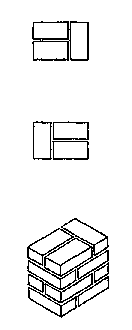
Fig. 59 b: Simple bonding pattern
for a 30x45 cm pillar.
Bonding patterns for large section pillars (45 × 45 cm or 60 × 60 cm) use the three-quarter block in classic designs. Simplified patterns can require only the use of a full block.
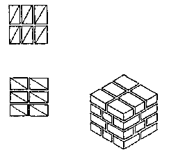
Fig. 61 a: Classic bonding pattern
for a 45 × 45 cm pillar.
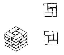
Fig 61 b: Simplified bonding pattern
for a 45 × 45 cm pillar.
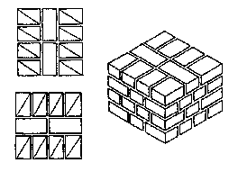
Fig. 61 c: Classic bonding pattern
for a 60 × 60 cm pillar.
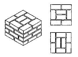
Fig 61 b: Simplified bonding pattern
for a 60 × 60 cm pillar.
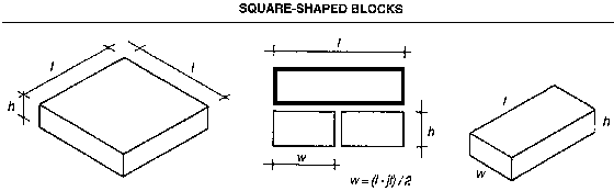
Fig. 62: Squre block and half block
obtained by cutting it down the middle.
The square compressed earth block is derived from the traditional adobe brick of the same shape and which is used notably in Latin American building cultures which have their roots in pre-Columban history (Peru, Columbia, Equator, Bolivia). Recent presses allow moulds to be modified for square shapes. This shape is very useful for reinforced building systems and has been used in model earthquake resistant housing operations in Peru and in the Philippines, as it enables vertical reinforcement made of wood or steel to be easily inserted into the thickness of the walls.
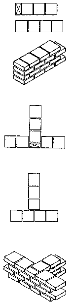
Fig. 63 a: Corner of wall.
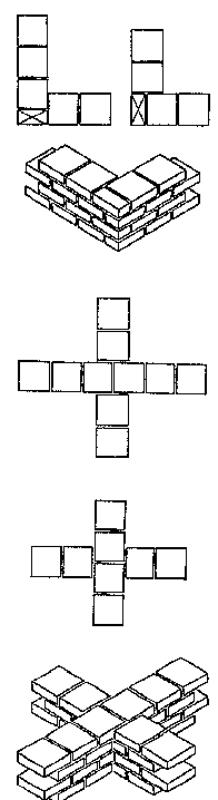
Fig. 63 b: Walls crosing in "X"
configuration.
Building using small masonry elements has the advantage of great flexibility in use resulting from a complete mastery of the modular use of the material. This modulation combined with the dimensioning of building systems can be determined as a function of the size of the building element, i.e. of the compressed earth block. It can also be determined as a function of the principles of the block bonding patterns which are used in the development of building systems.
"Coursing" is the link which the designer establishes between the dimensions of the compressed earth block, the dimensioning of the building systems, and their architectural representation in plan, elevation, section or detail. Coursing a compressed earth block architectural plan is indispensable when preparing working drawings. It ensures good project control in several ways:
- Coursing enables one to establish exact dimensions for the working drawings, in plan and elevation, and thus to obtain precise quantitative data for the project. A well coursed set of working drawings will be put to good use at the later stage of producing the compressed earth blocks for the execution of the work on site, by specifying the exact number of blocks required. It will also enable losses resulting from too much waste during cutting to be monitored by specifying how many full, 3/4 and 1/4 blocks are required. - By enabling the implementation of the works and the quality of the building systems used to be controlled, coursing enables one to determine the exact dimensions of bays in the walls (door and wall openings), the position of a ring-beam, the location of floor beams in a wall etc. All this precision will be apparent in the quality of the finished structure.
- It contributes to the appearance of the project, by highlighting the attractiveness of the material in the masonry of a visible compressed earth block wall. Precise modulation, thanks to coursing, underlies the aesthetic effect of all masonry using small elements which results from the appearance of rythmic sequences in the visible wall.
COURSING, BONDING PATTERNS, MODULATION AND DIMENSIONING
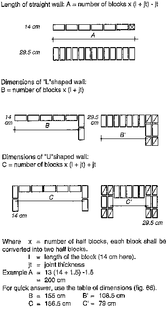
Fig. 65: Rules for quantifying
straight, "L" and "U" shaped walls.

Fig. 66: Table of dimensions of
straight, "L" and "U" shaped walls.
COURSING THE PLAN
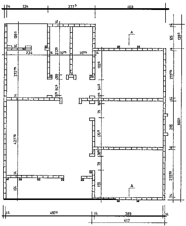
Coursing the geometrical representations of the working drawings for a compressed earth block masonry structure starts with the coursing of the plan. This is done with a carefully prepared working drawing. The scale of the working drawing should be such as to make it easy to read. For this reason 1/50 (2 cm/m) is often preferred over 1/100 (1 cm/m).
Coursing the working plan must be done "globally" and not in a fragmented way, which could result in confusion when trying to bring together the different fragments of the quantified plan.
Coursing the plan is done for each different course of earth blocks and generally for the "first" and "second" courses. But it is also often necessary to determine precise quantities for block courses located in a particular position in the future building, for example ring beam courses, when it has been decided to use lost formwork built from earth blocks. Another example would be a structure erected with thick ground floor walls, and less thick first floor walls. Note that the modulation of the openings is done using the nominal (or work) dimensions of the earth block used and that their dimensioning is done flush with the inside edges of the reveals for openings.
Dimensions of the coursed plan result from the application of
rules of modulation and of dimensioning (see figs. 65 and 66, p.
29).
Coursing a plan assuming the use of a parallelepiped earth block measuring 29.5 × 14 × 9 cm, and 1.5 cm mortar joints. The wall thickness is equivalent to 1/2 a block.
FIGURE
COURSING ELEVATIONS
The vertical coursing of the facades, working up from the plan, is just as important and indispensable as coursing the plan. It provides the exact number of earth block courses and enables careful control of the vertical dimensions of the openings, the position of the ring-beam, the location of floor-beams in the walls, using the modulation of the height of the blocks and the thickness of the mortar joints. Certain building systems can be sufficiently complex to demand vertical coursing, in elevation or in section.
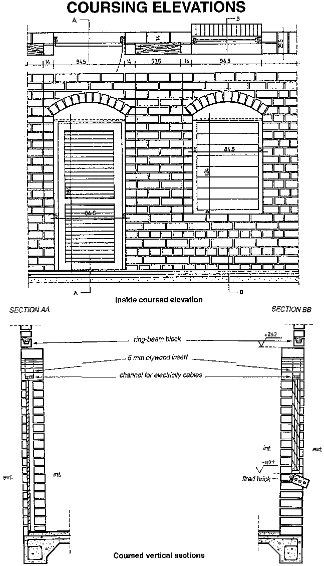
Fig. 68: Example of vertical coursing
of a façade and of vertical sections of a wall with
openings.
 |
 |
