Back to Home
Page of CD3WD Project or Back to list of CD3WD Publications
 |  |  | Formulae and Tables - Wood / textbooks for vocational training (GTZ, 122 p.) |  |  | 7. Hand Tools | |  | (introduction...) | | | 7.1. Measuring and Marking Tools | | | 7.2. Sawing Tools | | | 7.3. Planing Tools | | | 7.4. Mortising and Ripping Tools | | | 7.5. Drilling and Boring Tools | | | 7.6. Rasps and Files | | | 7.7. Other Tools |
|
Formulae and Tables - Wood / textbooks for vocational training (GTZ, 122 p.)
7. Hand Tools
Hand tools are individually guided working tools by means of
which action is taken on the object of work (workpiece) when the respective
operations are carried
out.
7.1. Measuring and Marking Tools
Marking tools serve the purpose of transferring sizes to the
workpiece and of marking the transferred sizes.
|
Tool
Representation |
Construction and use |
|
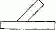
back square
 |
The back square serves for marking out right angles. It has a
shorter, thicker part (head piece, stop) and a longer, thinner blade (rail). It
consists of wood or steel. |
|
mitre rule
 |
Mitre rules serve to mark out 45° angles, with the shorter
leg serving as stop. |
|
bevel gauge
 |
Bevel gauges are back squares where both legs can be adjusted to
each other as desired (angles of any size can be formed). |
|
scratch gauge
 |
The scratch gauge serves for marking out straight scribed
linears parallel to one side of the workpiece. The stop is adjustable and is
arrested by wedges or screws. |
|
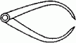
Compasses
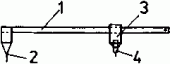 |
The compasses serve for taking and transferring sizes and for
marking out circular arcs. |
|
1 guide beam, 2 centring point, 3 slide, 4 pencil holder
|
|
|
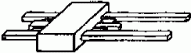
vernier caliper with depth gauge
 |
Length measurements are possible by placing the workpiece
between graduation carrier and sliding member. The diameter of bore holes can be
measured with the sensing elements. For determining the depth of bore holes and
similar the depth gauge is used. |
|
1 measuring surface of the graduation carrier, 2 measuring
surface of the sliding member, 3 sensing element for determining the diameter of
bore holes, 4 depth gauge |
|
|
outside caliper
 |
caliper-like measuring instrument (caliper) with inwardly bent
legs for tracing and comparing diameter, lengths and tick-nesses |
|
inside caliper
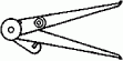 |
caliper-like measuring instrument (internal caliper gauge) with
outwardly bent leg points for tracing and comparing bore holes, counterbores and
similar |
|
radius gauge/profile gauge
 |
Radius gauges are templates like profile gauges and similar, by
means of which the profiles of boards, but also of narrow surfaces can be
checked. |
7.2. Sawing Tools
Hand saws have triangular teeth and consist of tool steel. We
distinguish between span-web saws and saws without span web.
Parts of a saw without span web
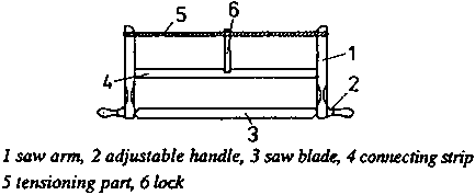
Figure 6 Parts of a span web
saw
Parts of a saw without span web
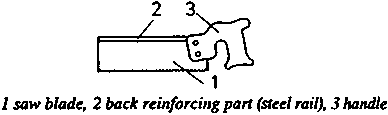
Figure 7 Parts of a saw
without span web
Kinds and dimensions of span-web saws (frame saws)
|
Kind of saw |
Saw blade |
|
|
|
|
|
length in mm |
width in mm |
thickness in mm |
Saw pitch in mm |
Setting width*) in mm |
Applications |
|
cabinet saw |
700;800 |
25 |
0.7 |
5 |
0.4 |
for work in grain direction; trimming, cutting off |
|
pad saw |
700:800 |
40 |
0.7 |
4 |
0.25 |
finer cuts across the grain direction, for wood-based materials
|
|
fret saw |
700 |
10 |
0.7 |
3 |
0.25 |
for sawing out bends |
*) tooth set: alternate bending out of saw teeth to
reach a cutting width which is greater than the blade thickness.
Kinds and dimensions of saws without span web
|
Kind of saw |
length in mm |
Saw blade width in mm |
thickness in mm |
Saw pitch in mm |
Setting width in mm |
Applications |
|
foxtail
 |
250-500 |
|
0.7-0.8 |
3-5 |
0.2-0.25 |
fine work, cutting of plywood and other materials |
|
keyhole saw
 |
300 |
|
1.0 |
4 |
0.35 |
for cutting out openings |
|
fine saw
 |
250 |
65 |
0.5 |
1.5 |
0.15 |
especially for mitre cuts |
|
back saw
 |
300 |
100 |
0.7 |
3-4 |
0.2 |
like fine saw |
nest of saws: Saw blades of all span-web saws known
so far can be fixed to a handle as required.
Tool geometry of hand saws
|
Kind of saw |
Angle at the a tool cutting edge in ° |
|
a |
b |
g |
|
cabinet, pad, fret saws |
45 |
70 |
-25 |
|
foxtail saw, keyhole saw |
60 |
60 |
-30 |
|
fine saw |
65 |
50 |
-25 |
|
back saw |
10 |
60 |
20 |
Recommendations for maintenance and use
Untension frame saws after use, turn the row of teeth inwards
during transport, saturate wooden parts with linseed oil varnish or with polish
to prevent impurities from getting into them; keep hand saws in a hangig
position, clean the saw blade from impurities by means of petroleum or similar
and protect it against rust by means of acid-free grease. Cover the teeth of
saws without span web during transport and storage so that no injuries are
possible.
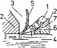
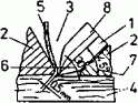
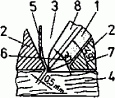
7.3. Planing Tools
Parts of a plane
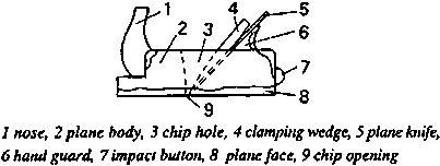
Figure 8 Parts of plane
|
Kind of plane |
Cutting angle d in
º |
Applications |
|
finish plane
 |
45 |
without flap; coarse chip removal, for flattening and rough
smoothing, chip thickness up to 1 mm |
|
1 plane knife, 2 plane body, 3 chip hhole, 4 workpiece, 5
chip, 6 wedge angle, 7 cutting angle, 8 flap of the plane |
|
|
|
double iron plane
 |
45 |
with flap, smoother surface than with the finish plane, for
flattening of finished surfaces |
|
1 plane knife, 2 plane body, 3 chip hole, 4 workpiece, 5
chip, 6 wedge angle, 7 cutting angle, 8 flap of the plane |
|
|
|
trying plane |
45 |
with flap; basically a long double plane; for dressing of
surfaces, for edging and jointing of narrow surfaces |
|
smoothing plane
 |
49 |
with flap; for smoothing of surfaces, for planing of end
surfaces |
|
1 plane knife, 2 plane body, 3 chip hole, 4 workpiece, 5
chip, 6 wedge angle, 7 cutting angle, 8 flap of the plane |
|
|
|
rabbet plane
 |
45...48 |
simple rabbet plane without flap, double rabbet plane with flap;
for replaning and resmoothing of rebates |
Recommendations for maintenance and use
Regularly clean the plane iron and the face of the plane; when
putting the plane down, lay it on its side; the face of the plane must be even,
if not, dress it and afterwards oil it slightly; replace faces of planes that
are excessively worn by new ones; if the plane is blocking, check whether the
flap is tightly fitting, the wedge is fitting or whether the pressure of the
wedge is properly acting on the lower part of the plane
iron.
7.4. Mortising and Ripping Tools
Mortising and ripping tools are hand tools for chiselling,
mortising and turning operations.
Parts of the mortising and ripping tools
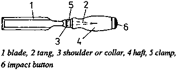
Figure 9 Parts of the
mortising and chiselling tools
Kinds and dimensions of the mortising and ripping tools
|
Tool |
|
Dimension of the blade |
|
|
|
width in mm |
thickness in mm |
Applications |
|
ripping chisel
 |
light medium heavy |
4...50
6...40
20...35 |
2.5...4
3.5...4.2
4.2...5 |
for mortising recesses, for recessing fittings, for mortising
recesses at an acute angle |
|
mortise chisel
 |
|
2...26 |
12...15 |
for mortising orftenon holes and similar |
|
turning chisel, flat
 |
|
4...50 |
3.5; 4.5 |
making of turned bodies, soft wood working, finishing
work;
a = 10...20º
b = 20...30º |
|
turning chisel, hollow
 |
|
4...50 |
3.5...6 |
hard wood working, roughing work;
a = 10...20º
b = 40...50º |
Recommendations for maintenance and use
The tool must be clean and sharp; always clamp the workpiece,
always chisel on the carpenter’s bench plate, not on the collets; further
hints: like plane
irons.
7.5. Drilling and Boring Tools
Drills are tools for making round holes.
Parts of a drill
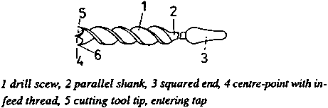
Figure 10 Parts of a drill
|
Drilling and boring tool |
Dimensions in mm |
Applications |
|
twist drill with roof-shaped point

|
diameter thread length |
3.0...8.3 42...70 |
for drilling into hard wood and end-grained wood, into
wood-based materials and metals |
|
twist drill with a spiral flute
 |
diameter overall length |
2...12 120...170 |
for drilling into end-grained wood |
|
auger bit
 |
diameter length |
6...30 185...250 |
for deep drilling into soft and hard wood |
|
twisted auger
 |
diameter length |
3...10 125...160 |
mainly for predrilling for woods screw into soft wood; produces
high splitting effect |
|
centre bit
 |
diameter length |
6...50 80...140 |
drilling into cross pieces |
|
grimlet
 |
diameter length |
2..10 90...200 |
for predrilling screw and nail holes, mainly into soft wood
|
|
wood countersinks
 |
diameter length |
16 and 20 100 |
for reaming bore holes, these get a funnel-shaped bevel |
Aspects for the drill selection
|
Feature |
Application |
|
with square shank |
for breast drill |
|
with parallel shank |
for drill chuck and machine |
|
with entering tap |
for cross-piece drilling |
|
with chip groove |
for deep drilling |
|
with roof-shaped point |
for non-fibrous materials and end-grained wood |
|
with centre point |
for exact advance |
|
with feed thread |
for manual work |
|
without feed thread |
for machine work |
|
with short die head |
for flat drilling |
Recommendations for maintenance and use
Drilling and boring tools must be clean and well sharpened. When
storing them, protect cutting parts. Keep them safe in a hanging or lying
position in cabinets or cases, they must not contact each other. Remove
impurities with hot water or petroleum after use, slightly grease them with
acid-free grease against
rust.
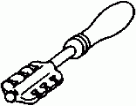
7.6. Rasps and Files
Rasps and files are hand tools for flattening and smoothing.
Rasps have coarser cutting edges, files have finer ones.
Parts of rasps and files
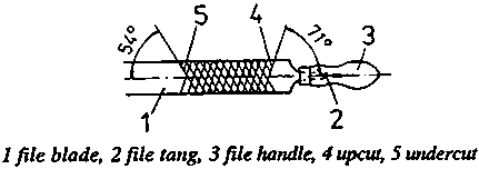
Figure 11 Parts of rasps and
files
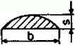
Kinds and dimensions of rasps
|
Tool |
Length in mm |
Cross-section in mm |
Application |
|
flat rasp
1 width, 2
thickness |
200...350 |
20 × 5...36 × 8 |
Rasps serve for coarse smoothing of round portions and recesses.
|
|
half-round
1 width, 2
thickness |
200...300 |
18 × 6...30 × 10 |
|
|
round rasp

1 width |
200...250 |
diameter 8 and 10 mm |
|
Kinds of dimensions of files
|
Tool |
Length in mm |
Cross-section in mm |
Application |
|
rectangular file
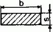
1 width, 2
thickness |
200 and 250 |
20 × 3.5; 25 × 4 |
for fine smoothing of round portions and recesses, reworking of
rasped surface |
|
flat/round file
1 width, 2
thickness |
like rectangular file |
|
|
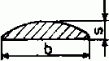
|
triangular file

1 width
|
100...200 |
side length 6...17 |
especially as saw sharpening file, edge angle 60°, edges
slightly rounded for machining the tooth gullet |
Special kinds, e.g. as special saw and mill
files
Recommendations for maintenance and use
Use only tools the tangs of which are straightly and firmly
seated in the haft (stab injuries). Work in grain direction, if possible. Choose
tooth spacing*) according to the wood quality (use files with coarse cut for
soft or damp wood). Clean the tools from impurities by dipping them into hot
water, brush them with a hand brush. Clean metal files with file brushes made of
fine copper wires.
*) Cuts: Cutting edges lying closely one after the
other and recessed or cut into the metal base body by
machine.
7.7. Other Tools
|
Tool |
Application |
|
glass cutter
 |
for cutting glass panels.
The glass is scratched under slight
pressure by means of a diamond particle or a hard metal tip. |
|
setting iron
 |
for setting hand saws. The tool head provided with the recesses
may have a varying number of notches; the notches are of different widths and
correspond to the different thicknesses of the saw blades. |
|
setting pliers
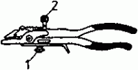
1 adjusting screw
for tooth depth 2 adjusting screw for setting width |
for setting hand and machine saw blades. The setting pliers are
designed for various tooth depths and blade thicknesses; setting depth and
setting width can be adjusted. The setting pliers allow more exact working than
the setting iron. |
|
setting pliers for tooth depths of up to 8 mm and blade
thicknesses of 0.3...1.5 mm

1 adjusting screw
for tooth depth 2 adjusting screw for setting width |
|
|
setting pliers for tooth depths of up to 15 mm and blade
thicknesses of 0.5...3.0 mm |
|
|
hone
 |
for honing (smoothing) the cutting edge.
Natural as well as
synthetic stones are used, with the latter mostly having on both sides different
grain sizes (rough honing, fine reworking). Water and oil are used as
lubricants. |
|
scraper |
for smoothing hard wood surfaces.
Chip removal by sharp burrs
on the longitudinal edges; 0.8 - 3 mm thick, made of tool steel |
 |
 |
