Back to Home
Page of CD3WD Project or Back to list of CD3WD Publications
 |  |  | Wells Construction: Hand Dug and Hand Drilled (Peace Corps, 1980, 282 p.) |  |  | Section two: Hand dug wells | |  | Chapter 2: Introduction to hand-dug wells | | | Chapter 3: Well design | | | Chapter 4: Supplies | | | Chapter 5: Lowering and raising workers and equipment | | | Chapter 6: Digging | | | Chapter 7: The middle section: overview of lining techniques | | | Chapter 8: Construction of the middle section | | | Chapter 9: Construction of the bottom section |
|
Wells Construction: Hand Dug and Hand Drilled (Peace Corps, 1980, 282 p.)
Section two: Hand dug wells
Chapter 2: Introduction to hand-dug wells
A. Overview
Rural communities have frequently employed hand-dug wells to
increase the supply of water available for individual use. Using simple
construction techniques and suitable materials, hand-dug wells can provide
reliable sources of water and offer the following advantages:
· Because the
community can be involved in the actual construction, it is "their" well, which
they are more likely to maintain.
· The equipment
needed is light and simple and thus suitable for use in remote
areas.
· The construction
techniques are easily taught to unskilled workers, thus cutting supervision
time.
· With the
exceptions of cement and reinforcing rods, the necessary materials are usually
locally available, making it one of the cheapest methods of wells construction
in a rural community.
· A completed well
provides a reservoir at the source which will accumulate and store water from
aquifers that would otherwise be too weak to use.
On the other hand, hand-dug wells present certain limitations:
· 60 meters is
usually the practical limit to the depth that can be reached, although most dug
wells are less than 20 meters deep.
· Construction is
slow.
· Extracting large
quantities of water with motorized pumps is not feasible.
· Hard rock is very
difficult to penetrate and often can only be accomplished by blasting, which is
slow, hard work.
· Because it is
difficult to penetrate very far into the aquifer, slight fluctuations in the
water table often make hand-dug wells unpredictable and unreliable.
The hand-dug well is the only method of well construction where
people actually go into the well to work educational campaign to demonstrate and
explain what each part of the well is and how it works might help villagers
understand and then want to work with and maintain it more. In so doing, proper
maintenance necessary in keeping the well functioning might be better carried
out, particularly in communities using a well or an improved water source for
the first time.

Figure
For sanitation reasons a pump is desirable. If installed on a
hand-dug well with a full cover, a pump will help reduce chances of
contamination significantly. In rural areas where pump maintenance and repair
can be a real problem, large diameter wells are often the best solution to water
supply problems. Pumps can be installed while leaving an accessway through which
water can be drawn by rope and bucket if the pump should break down. (See Pumps
Appendix).
Compared to other well sinking methods, digging a well by hand
takes a long time. An organized and experienced construction team consisting of
five workers plus enough people to lower and raise loads in the well can dig and
line 1 meter per day in relatively loose soil that does not cave in. However,
the bottom section is likely to take 2 or 3 days per meter because of the
difficulty in working while water continually enters the well. Depending on how
you plan to develop the well, the top section can take anywhere from a day or
two to several weeks. An experienced team sinking a 20 meter well and installing
pulleys on the top structure could easily take 5 weeks, including occasional
days off (this, of course, assumes no major delays). A new or inexperienced
group would be expected to take twice that time.
Hand-dug wells should be dug during the dry season when the
water table is likely to be at or near its lowest point. The well can be sunk
deeper with less interference from water flowing into it. The greater depth
should also ensure a year-round supply of water.
If the well cannot be dug during the dry season, plan to go back
to it at the end of the dry season to deepen it.
B. Work Outline
Outlined below are the major steps involved in digging a well.
The appropriate community leaders, health committee, public works committee, and
others who are interested should be involved in all the planning decisions.
· Begin community
education and awareness activities to enable the people to understand what is
happening and how they can benefit.
· Choose a well site
based on geological factors, user preference, sanitary conditions, and
accessibility.
· Determine
available expertise - people (including yourself) with well or general
construction experience.
· Assess materials
available - tools, cement, reinforcement rods (re-rods), sand, gravel,
wood.
· Select methods of
construction that are most suitable for the use and available materials,
considering shape, size, depth, lining, bottom, and top.
· Plan and begin any
training that will be necessary for workers.
· Before
construction begins, put down in writing the workplan for the construction of
the entire well.
· Gather all
equipment and materials needed for construction of the well at the well site.
Arrange these at the site so as to facilitate construction as much as
possible.
· If concrete lining
rings are to be used, begin constructing them in advance. Each ring must be
cured for at least 4 days before it is put in place at the well
head.
· Lay out the hole
with provisions for checking diameter and plumb (see p. 53).
· Arrange for people
and materials to get in and out of the well.
· Dig and line the
middle section.
· Continue the
digging and lining procedure until
(1) you reach water, or
(2) some obstruction causes you to
(a) change digging/lining procedure
(b) abandon
this well and pick a new site.
· Dig and line the
bottom section as far as possible into the aquifer. The method used to dig and
line the bottom section will often be different from the digging and lining
method used in the middle section. This may be necessary because you are not
only concerned with digging, lining, and possible hole collapse (as in the
middle section), but also with removing enough water from the well to permit
work to continue.
· Install a simple
sand and gravel filter or porous concrete plug across the bottom of
hole.
· Extend the lining up above ground to
form the head wall.
· Build and install the
well cover.
· Install the pump in the cover
on the well.
· Disinfect the well.
· Build the apron (platform) around the head wall to
channel the run-off to one particular place.
· Build a drainage pit or other device for removal of
standing water.*
· Build an animal
trough.*
· Build a wash-basin
platform.*
*These items are not always necessary but should be
considered.
Chapter 3: Well design
A. Introduction
To design a well, it is necessary to decide what materials will
be used and how they will be put together. This includes determining:
· the size and shape
of the hole;
· which digging and
lining methods will be followed;
· how much water
needs to be available, and, therefore, how deep the bottom section should go
into the aquifer;
· how the top
section should be constructed to best protect the well from contamination, while
allowing easy access to water by those who will use the well;
· the anticipated
well depth.
This chapter discusses the decisions that must be made and
presents options for consideration.
B. Well Shape
The shape of the well is what it would look like if you were
looking straight down into it.
C. Well Size
The size of the well is a measure of how wide it is. Some holes
are very large, and some are very small. The size will be largely determined by:
(1) the way it is excavated, (2) the materials used to line it, and (3) the
purpose of the well.
The size of the round hole is usually expressed by its diameter,
a measurement from one edge of the hole through the midpoint of the well to the
other side of the circle. (See Figs. 3-2 and 3-3.)
Although wells can be dug in any shape, almost all wells are
round. The reason for this is that a round well produces the greatest amount of
water for the least amount of work. Also, a round lining is the strongest that
can be built for the smallest quantity of materials. Thus, while other well
shapes have been used without problems, a round shape enables the builder to get
the most from available time, money, and materials.
Square or rectangular wells are usually dug where materials to
be used in lining the well necessitate such a shape. This is most often the case
when flat wood board" are the only lining materials available. Wood, however, is
not recommended for several reasons which will be discussed later. (See p. 74.)
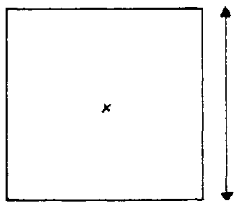
FIG. 3-1. SQUARE WELL
Well Size-Diameter
Before the actual digging work begins, the exact diameter of the
hole must be decided (see Figs. 3-2 and 3-3).

FIG. 3-2. ROUND WELL
FIG. 3-3. DIAMETER IS THE LONGEST
MEASUREMENT ACROSS THE HOLE
Many factors could determine which diameter should be used.
· If there is a
government-sponsored organization or agency which does wells construction using
a standard diameter, you should consider using the same diameter. Doing so will
make the eventual incorporation of the well into community and government
planning and development much easier.
· If forms or
pre-cast lining sections are available, you might consider using them. It would
necessitate choosing an appropriate diameter for the particular equipment you
have. However, if the former situation (mentioned above) also exists, it should
in most cases receive priority.
Generally, the choice of diameter will be based on two
considerations. The well should have (a) the smallest diameter which still
provides (b) a comfortable working space for the number of people that will be
working in the well at one time.
a. The smaller the diameter of the well, the less soil and rock
will have to be dug and the less materials will be required to line the well.
Remember, if you double the diameter of the well, you increase the amount of
soil and rock that must be dug by four times. For example, as indicated in the
table below, a 1.0-meter diameter well 20 meters deep requires removal of 15.7
cubic meters (m³) of material while a 2.0meter diameter well 20 meters deep
will require the removal of 62.8 m³.
Diameter x Diameter x 0.7854 = Area.
Area x Depth = Volume
|
Diameter |
Area |
Depth |
Volume |
|
1.0 m |
0.79 m² |
20 m |
15.7 m³ |
|
1.1 |
0.95 |
20 |
19.0 |
|
1.2 |
1.13 |
20 |
22.6 |
|
1.3 |
1.33 |
20 |
26.6 |
|
1.4 |
1.54 |
20 |
30.8 |
|
1.5 |
1.77 |
20 |
35.4 |
|
1.6 |
2.01 |
20 |
40.2 |
|
1.7 |
2.27 |
20 |
45.4 |
|
1.8 |
2.54 |
20 |
50.8 |
|
1.9 |
2.84 |
20 |
56.8 |
|
2.0 |
3.14 |
20 |
62.8 |
b. The workers will need enough space so that they are not
hampered in their work. There must be enough space for them to use their tools
and for the bucket which will remove excavated materials from the well. Without
enough space, they will continually bump into each other and the wall. During
stages of its construction, a well may have two or sometimes three different
diameters (see Fig. 3-4).
(1) The hole is dug to the diameter decided upon.
(2) When a lining is installed, the diameter is further reduced
along with the available working space.
(3) You may be installing the bottom section lining inside the
existing lining. This will further reduce the diameter.

FIG. 3-4. THREE DIFFERENT WELL
DIAMETERS USED DURING CONSTRUCTION
D. Ground Conditions and Lining
It is very difficult to anticipate what the final depth of a
well will be before it is begun. However, if there are other wells in the area,
it is possible to get an idea of the approximate depth of the water table. This
can be a great help when gathering supplies needed for lining construction,
because it will enable you to stockpile approximately enough materials to
complete the well.
All wells, except those drilled through rock, can be expected to
cave in with time unless a lining is installed to support the well. The lining
thus helps to keep the well open. There are certain acts of nature, such as
earthquakes or even gradual ground shifts, which will break even the strongest
linings, but these cannot be planned for or anticipated. Occasionally slight
ground shifts can put pressure on linings causing them to split and separate if
not strongly built. Geologists can usually predict where such shifts are likely
to occur. If no such information is available, it is recommended that you build
the lining strongly enough to withstand normal earth stresses.
Depending on ground conditions, you may or may not be able to
dig the complete hole and then line it. In very loose sandy soil, for example,
the sand from the walls of the hole will frequently cave into the hole,
seriously hampering efforts to deepen the hole. There are often relatively
simple methods of dealing with such problems (see p. 58).
Designing the lining for the middle section is largely a matter
of assessing the ground conditions and materials availability to determine the
lining materials and method most appropriate for the situation.
1. Ground Conditions
· Very loose soil
(example: dry sand) - the hole is as wide as the hole is deep because its sides
continually collapse and cave in (Fig. 3-5a).
· Loose soil
(example: damp sand) - a relatively shallow (1 to 5 meters) hole can be dug
before its sides may cave in Fig. 3-5b.
· Firm soil
(example: compacted clay and sand mix) a hole can be dug to the water table with
minimal danger of collapse and cave in Fig. 3-5c.
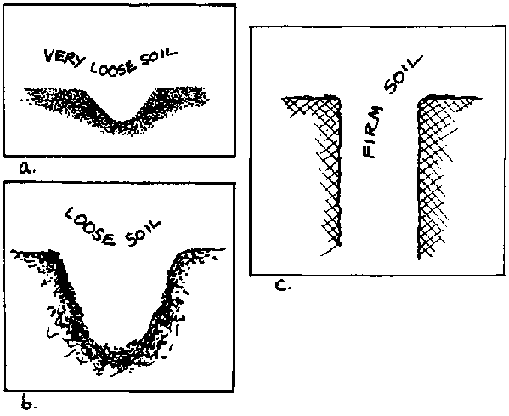
FIG. 3 -5. GROUND CONDITIONS
Unless you have had substantial experience digging in the area
and this particular type of soil, or have been trained in the identification of
soils and their properties do not leave the hole unlined for more than 5 meters.
The only possible advantage to digging the entire hole first is
that you can then be certain that water can be reached before you start using
your often expensive materials to line the well. However, if there is any
question about the safety of working in an unlined section of the well, it is
not worth the gamble to leave it unlined.
2. Dig and line options
· Dig a short
section and line
One source has suggested that for safety reasons, no more than 5
meters of a well should be dug and left unlined. More commonly, this cautious
method is used in loose soil. This means of construction is also recommended in
all soils when workers are inexperienced. Using this method, wells are dug in
0.5 to 5 meter sections, and then lined.
· Dig to water table
and line
This method is commonly used in firm soil, especially where the
water table is not very deep. It has the previously mentioned advantage of not
using any expensive materials in a well until a good supply of water can be
assured. However, this method should not be attempted by workers inexperienced
with well work.
· Dig complete well
and then line
This method is not recommended because of the danger of cave-ins
beneath the water table which would undermine the entire well shaft. The only
situation in which this method might be justified is where the middle section
lining must rest on the bottom section lining for support, but there are many
ways of avoiding that necessity.
E. Design: The Bottom Section
There are two basic methods for constructing the bottom section
- sink lining and dig-and-line.
1. Sink lining into place. Advantages include:
· The method
protects workers from cave-ins during sinking;
· Workers in the well can put all their effort into
removing soil and water, presumably allowing greater well penetration into the
aquifer.
A disadvantage is the possibility that workers may have
difficulty in firmly attaching the rings together. (See lining rings, Fig. A.)
2. Dig and then line. Advantages include:
· The method
requires less special ,reparation;
· The
bottom section lining attaches directly to the lower part of the middle section
lining, thus producing a stronger, continuous structure.
The disadvantages include:
· Workers probably
cannot get as far into the aquifer as in the other method because of the
necessity for workers to remove soil and water and place reinforcing rod and
concrete at the same time;
· There is greater
possibility of cave-ins because of a need to work beneath concrete that has not
had time to completely set;
· The method may
require special fast-setting cement so as not to be washed away by water
entering the well.
The purpose of the bottom section is to allow as much water as
possible into the well without permitting any of the fine soil particles from
the surrounding aquifer to enter the well.
There are three commonly used methods of allowing water to enter
the well. (See Fig. 3-6.)
· Through porous
concrete lining - Lining rings sunk into the bottom section can be made of
porous concrete which acts as a filter to prevent soil particles from entering
the well.
· Through angled
holes in the lining - Holes can be punched in a freshly poured concrete ring
which, when cured, can be sunk into the bottom section. These holes are more
effective at preventing soil entry if they are slanted up toward the middle of
the well.
· Though the bottom
The bottom of the well should always be constructed to allow water to come up
through it. Often the bottom is simply left open and uncovered but it is
preferable to prevent soil entry and the gradual filling up of the
well.
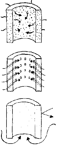
FIG. 3-6. WATER ENTRY INTO WELL
F. Design: Top Section
The purpose of the top section is to provide safe and easy
access to well water and to prevent as much contaminated surface materials as
possible from entering the well.
The design of the top section is strongly influenced by two
aspects of well usage: (1) access to water or how water is drawn from the well,
and (2) preventing, as much as possible, surface contaminants from entering the
water. These two functions are not always compatible. It is often necessary to
compromise sanitation for the sake of water access and community acceptance.
Obviously you want to do this as little as possible but not to the point of
jeopardizing support from the local community or government.
A top section, in fact, is not absolutely necessary for the
function of a well. However, the different design of the parts of the top
section is intended to make the well safer, cleaner, and more convenient for
users.
Here are the major components of the top section:
· Head
wall;
· Drainage apron (platform);
· Cover;
· Animal
trough;
· Wash basin.
1. Head wall
A head wall should be built on all wells which will not be
fitted with a permanent cover and a pump as a simple inexpensive safety feature
which will prevent people and animals from accidentally falling in.
This is simply a wall which extends above the surface of the
ground far enough to prevent most accidental entry of people, particularly
children, and animals. Its external dimension is dependent on how thick you want
the head wall to be. A head wall that is unnecessarily thick will encourage
people to stand on it to draw their water, creating an unsafe situation. The
easiest and best way to construct the head wall is as an extension of the
lining. In most cases it will be convenient to build the head wall as an
extension of the lining above ground. You will already have the equipment and
supplies on site with which to do this. The head wall should extend 80 to 100 cm
above the ground surface or apron, if there is one (see Fig. 3-7).
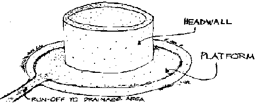
FIG. 3-7. TOP SECTION
2. Drainage apron (platform) (See Fig. A.)
A drainage apron is most often a reinforced concrete slab 1 to 2
meters wide which surrounds a well and, because of its slight slope, channels
surface water away from the well. Wire mesh reinforcing may be used if it is
available.
By forcing water to flow away from the well, the apron serves
two functions:
· It prevents
contaminated surface water from following the outside of the lining and flowing
back down into the well before it has had a chance to be sufficiently filtered
by the earth.
· It prevents the
formation of a mucky area immediately around the well which can be a breeding
ground for disease and a source of contaminants to the well water.
A sloping platform (Fig. 3-8) will simply move the mucky area
from direct contact with the head wall to the edge of the platform. It will
still be an eyesore and health hazard, although not so much as if it were right
next to the well.
By installing a shallow channel (Fig. 3-9) or very short wall
(Fig. 3-lO) around the edge of the platform, the water can be funnelled off to
one specific area away from the well where people and animals will not have to
track through it to get to the well.

FIG. 3-8. SLOPING PLATFORM

FIG. 3-9. SHALLOW CHANNEL
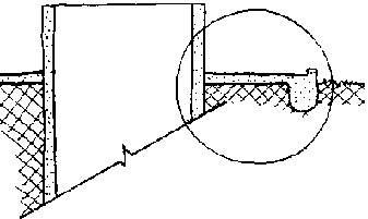
FIG. 3-10. SHORT WALL
The apron should be strongly and carefully constructed as it
will receive a lot of wear, and any cracks or chips which develop will decrease
the effectiveness of the apron.
An apron can be built of stone with mortared joints if cement is
in short supply. If for some reason it is not feasible to build an apron, dirt
should be built up around the well so that water spilled will tend to run off
away from the well rather than collect around it.
3. Cover
A cover can improve the sanitary quality of the water in the
well by preventing the dust and dirt normally carried in the air from entering
and contaminating the water. It also prevents people from dropping things into
the well.
There are two basic variation of well coverstemporary
(removable) and permanent (fixed in place).
· A temporary cover
would be one that covers the well between the times it is being used, but must
be removed to pull water from the well. For example, a temporary cover would be
a wooden cover that rests on top of the well but must be removed to throw a
bucket, tied to a rope, into the well. This is a limited step toward protecting
the well water from surface contamination.
· A permanent cover
is usually made of reinforced concrete. It can be poured in place on the well or
pre-cast in one or more pieces and later set over the well. (See Fig. 9-9.) Pump
mounting bolts and an access door can be cast into the concrete. Pre-casting the
cover in one or two pieces may be easier because of the difficulty of building a
form which is both strong enough to support the weight of the concrete over the
open well and which can then be removed after the concrete has set.
4. Drainage pit
In some areas it may be necessary to construct a special
drainage pit to allow spilled and run-off water to soak into the ground. This
may be used where other measures cannot feasibly prevent the build-up of
standing water. If such a pit is deemed necessary, make sure that it is at least
10 meters from the well. The pit can simply be a hole dug in the ground which is
then filled with loose rock and gravel.
NOTE: Where the water table is less than 3 meters from the
surface, a drainage pit should not be dug because of the danger of directly
contaminating the water supply.
5. Animal trough
If an animal trough is necessary, it should be built far enough
from the well so that neither the animals nor their dung will collect around the
well and thus contaminate the water.
6. Wash basin
It may be useful to build a wash basin if clothes washing is
done at the well. It is important to prevent wash water from pouring back into
the well and thus contaminating it. The basin should, therefore, be watertight
and built at an elevation below the mouth of the well. Where there is no place
to build a basin below the level of the well, it can be located 10 meters from
the
well.
Chapter 4: Supplies
A. Introduction
Supplies include the materials, tools, and equipment necessary
for construction of the well.
The following supplies will be needed for construction of any
hand dug well:
· digging fools -
shovel, pick, mattock;
· equipment to lower
and lift people and supplies in and out of the well;
· construction material and the tools needed to work
with it.
Tools that may be used with the various materials include the
following:
· reinforced
concrete - cement, sand, gravel, forms, reinforcing-rod, tie wire, re-rod
cutter, re-rod bender, wire cutters, pliers, buckets, 1 trowel (2 would be
better), mixing hoes, aggregate gauge box;
· concrete - cement,
sand, brick or rock, mixing area, buckets, trowel, mixing hoes, aggregate gauge
box;
· wood - wood, saw,
nails, hammer.
B. Tools and Equipment
· lowering equipment
- tripod, headframe or pulley support with pulley;
· cable or rope - 12 mm steel or 25 mm hemp;
· buckets - 1 large, 2 small;
· square nosed shovel (mixing);
· round nosed shovel (digging);
· hammers
· hard hat
for each worker in well;
· spare shovel and
hammer handles'
· plumb bob and plumb line;
· level.
C. Materials
1. Cement
Most of the lining methods discussed here rely on the use of
cement in one form or another, including concrete, mortar, and porous concrete.
For the construction of permanent, sanitary hand-dug wells, cement compounds are
the only materials in common use around the world. There is no other material so
readily available worldwide that combines the strength, workability, and
adaptability of cement compounds. Without cement it will be very difficult to
build a permanent, sanitary water source. (See Cement Appendix, p. 221.)
a. Limited amount of cement available
Where there is a limited supply of cement available which will
not permit you to pour linings or build masonry, you might consider building a
loose rock or brick wall. Simply mortar the inside layer to prevent it from
falling into the well. This should only be attempted in very stable ground not
subject to collapse.
In some areas only the top 3 meters of the well needs to be
lined. This reinforces the area of the well which is most likely to cave-in and
uses a minimum of material, and it can be attempted only where a mortar or
concrete lining is built in place in a well which is being sunk in firm soil.
Wells lined like this are rarely more than 10 meters deep.
b. Cement Substitutes
Cement substitutes are sometimes commercially available or can
be manufactured locally. Lime, for example, can be mixed with sand and water to
form a mortar-like paste which can be used in laying brick or rock walls. Like
other cement substitutes, it does not have anywhere near the bonding strength of
cement mortar.
2. Other Materials
If you cannot get cement in a reasonable length of time and at a
reasonable cost, you should consider building the well with other materials such
as wood or unmortared rock. These other materials will not last as long as
cement but they will enable you to make water available where it is needed now.
· Unmortared brick
or rock
Many wells have been built of unmortared rock and have lasted
for hundreds of years. This, however, is only where highly skilled stone masons
and suitable rock are both available.
Normally unmortared brick or rock is only a temporary solution
which will collapse in time. Where the ground is very stable, you might consider
such a lining, although the well may stand unharmed without a lining for a long
time in this case.
· Wood
This also is only a temporary solution. It will rot soon (in 1-3
years), tainting the water and allowing caveins.
D. Organization of supplies at the well site
In your planning consider:
· the space needed
for each operation;
· the arrangement of
supplies within each operation space;
· which operations
must be performed at the same time so that their respective spaces do not
conflict or cross;
· that a different
lining method may be used for the bottom section which will require space for
working and materials.
There are 3 different types of operations which must be
performed during the sinking of a well:
· removing excavated
soil and rock and dumping it;
· lowering and
lifting people and supplies in and out of the well;
· preparation and placement of lining
materials.
The purpose of organizing the supplies around the well is to
provide comfortable working spaces for each of these operations where they will
not conflict with each other but are still close enough to be coordinated and
efficient. (See Fig. 4-1)
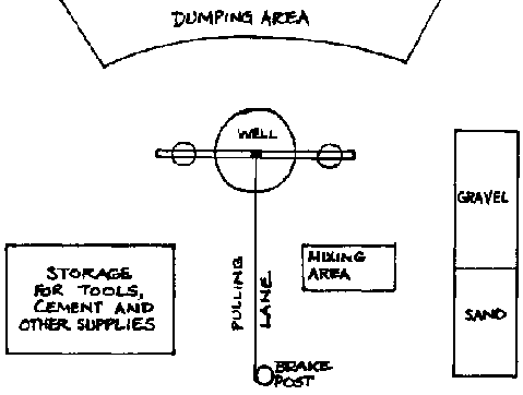
FIG. 4-1. LAYOUT OF MATERIALS AND
SUPPLIES
1. Removing excavated soil and rock and dumping it.
A great deal of time will be spent performing this same basic
operation over and over again. As a result workers will be tempted to do the
least amount of work necessary to get by. It is important that the dumping area
be:
· far enough away
from the well to not subject the well to danger of caving in;
· not so far away as
to slow well sinking because excavated material is not being dumped fast
enough;
· located so that
rain will not wash material back into the well;
· located in order
that water pulled from the well for sinking the bottom section will run off and
not collect near the well;
· large enough to
hold all the material taken from the well.
2. Lowering and lifting _people and supplies in and out of the
well.
This operation is critical for the whole well sinking process
but is also so flexible in its placement that too often it is simply assumed
that space can be found after everything is set up. Unnecessary delays and
possibly dangerous situations can be avoided in later work by simply arranging
the supplies so that nothing ever obstructs the lane the pullers must use to
raise and lower supplies in the well. Also avoid placing supplies so that they
must cross the pulling lane to be used.
3. The preparation and placement of lining materials.
Most hand dug wells need space to store and later mix sand,
water, gravel, and cement to form concrete. The actual mixing area should be
close to the well and next to the pulling lane to permit easy movement of
concrete into the well. The materials necessary for concrete should be stored
near the mixing area but far enough from the well to prevent danger of cave-ins.
Sand and gravel storage will take up a large amount of space,
which should preferably be easily accessible from the mixing area and from the
opposite side to allow for replenishment if necessary. Also, if you plan to use
pre-cast Lining rings, you will have to allow space for their construction.
The importance a few minutes worth of planning can have is
demonstrated in the following example.
Assume that we have a well with a 1.3m interior finish diameter,
a 7.5cm thick reinforced concrete lining, and a depth of 20m - an average sized
well. This well will require about fifty 50kg bags of cement for construction of
the middle and bottom section. If only complete bags of cement are mixed at a
time that will require:
· 50 trips to and
from the cement storage area;
· 50
wheelbarrow trips of sand;
· 100 wheelbarrow
trips of gravel;
· some multiple of 50 trips
to and from the water supply;
· about 500
trips with concrete from the mixing area to the well, depending on the size of
the concrete buckets.
Obviously the shorter all these trips can be, the less time and
energy will be consumed by them. Remember too that as you take sand and gravel
from the near side of the storage piles you have to walk farther and
farther.
Chapter 5: Lowering and raising workers and equipment
A. Introduction
At some point most materials and equipment involved in hand dug
wells construction will be lowered into or pulled out of the well. This
raising/lowering operation is so basic to wells construction that it will be
discussed here in some detail. (See Fig. 5-1)
The raising and lowering operation will eventually become
routine because it must be performed so often. Before the real well sinking work
is begun, you should try to plan that routine, by considering what equipment
will be used and how the workers should be organized to use the equipment
safely.
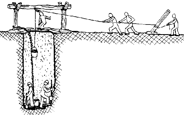
FIG. 5-1. RAISING AND LOWERING
OPERATION
B. Safety
Most major accidents or injuries that happen during the
construction of a well result from faulty raising and lowering procedures.
Accidents usually occur because someone forgot, didn't understand, or wasn't
ready to perform his/her part of the operation. Remember that people's lives
depend on how carefully this operation is performed.
There are many tools, pieces of equipment and items of knowledge
that can help in this operation by making it easier and safer. They include:
· tripod,
headframe;
· pulleys;
· winch;
·
rope-knots;
· buckets.
Everyone coming in contact with this raising/ lowering operation
should be thoroughly familiar with it. It is a good idea to do a couple of
practice runs so that everyone understands exactly what is involved. Switch
people around to help them understand what is happening at different points in
the operation. It is also useful to have well workers lowered in and out of the
well to help resist any later tendencies for joking while pulling on the rope.
That way, everyone understands the reality of being suspended on a rope with no
way to help yourself if a problem occurs.
Certain safety features should be followed:
· All workers in the
well should wear hard hats;
· People are most
safely raised or lowered in the well on a bosun's chair made of a board, log or
other appropriately strong seat firmly tied to a rope (see Fig.
5-2).
· Nothing should
ever be left lying on the ground near the opening of the hole. In a working
situation, people can easily trip and fall, knocking loose materials into the
well.
· It is also
necessary to be concerned with the safety of people other than the well workers.
Passersby have a natural curiosity and wish to find out what is happening.
Before construction is begun, it is very useful to establish some kind of
perimeter, or even a fence, which is to be crossed only by those actually
involved in construction. This may be difficult enough to enforce during working
hours but becomes more important and more difficult at night and on nonworking
days. It may then be necessary to use a guard to remind passersby that they are
not supposed to be in the area. The guard can also make sure that tools and
supplies are not taken from the site.
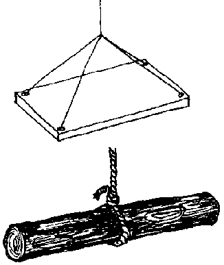
FIG. 5-2. TWO SUGGESTED DESIGNS FOR A
BOSUN'S CHAIR
It is very helpful to have a set of signals to control raising
and lowering. These should be voice commands as well as hand signals. Four
simple signals will usually cover most of your needs (see Fig. 5-3).
· raise;
· lower;
·
stop;
· slower.

FIG. 5-3. HAND SIGNALS
C. Lowering Supports, Tripod, Headframe
Some type of lowering support is necessary when digging, except
in very shallow wells. It provides a much safer and easier way to lower tools
and materials for use in the well and remove the soil and rock dug up in the
hole. Such a structure usually has 1 or 2 pulleys which can be suspended over
the center of the hole or offset. The offset arrangement is often easier to work
with.
Choose the type of lowering support most suitable for the kind
of work you expect to be doing and the materials you have available. (See Figs.
5-4, 5-5, and 5-6.)
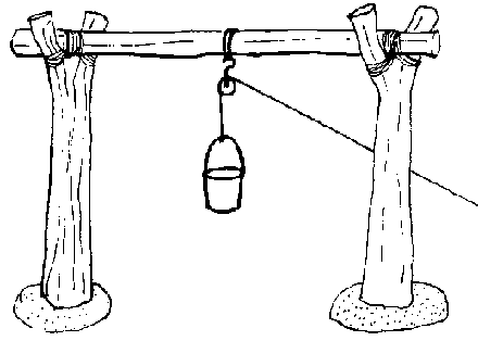
FIG. 5-4. WOOD LOWERING SUPPORTS
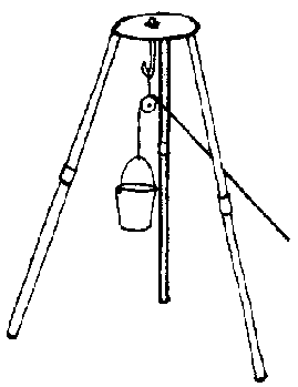
FIG. 5-5. TRIPOD
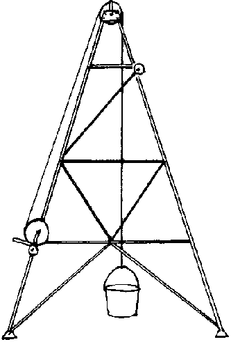
FIG. 5-6. HEADFRAME
If they will not obstruct other operations,the lowering supports
can be erected before you begin digging. Or, more often, erect them after you
have dug a meter or two and passing buckets by hand in and out of the well
begins to get difficult.
It is the operation of this unit which will largely determine
the safety of the workers in the hole. Emphasize this major point to all workers
and visitors at the well site. Also, observe these six points on safety:
1) Lowering and raising materials and people should
always be done with enough people on the rope. It is dangerous to rely on one or
two strong individuals. Using several people assures control of the load even
when a hauler trips or is otherwise unable to continue supporting the load, when
people are in the well, or when someone is on the rope being raised or lowered
in the well.
2) Someone should always be posted at the well edge, watching
the load being worked within the well. In case of a problem this person can
alert the haulers or other workers. The same individual could also hook and
unhook buckets, loads, and people from the rope and ease them into and out of
the well.
3) When pulling large buckets full of soil, rock and water from
the well, two people may be needed to pull the heavy bucket out of the well and
place it on the ground next to the well for later dumping.
4) There should be an established set of signals which the
person at the well head will use to direct those hauling on the rope. (See Fig.
5-3) These signals should be taken very seriously and are to be used only when
necessary, but with no hesitation when they are necessary. Practice in using and
understanding the signals is advisable.
5) Throughout the well sinking process be especially careful
that nothing falls into the well. Even a small pebble unknowingly knocked into
the well can cause serious injury to a worker at the bottom if it falls from a
distance. Take preventive measures. Be careful how you work around the edge of
the well.
6) Always leave a safety line hanging in the hole. This is a
rope tied off at the ground surface which can be used in an emergency as an exit
from the well.
D. Other Raising/Lowering Arrangements
While lowering supports have been found to be the easiest and
safest form of entry and exit, many other methods have been used. In these other
methods tools and materials are lowered by rope by people standing next to the
hole. People may be raised and lowered in this way but it is usually easier for
individuals to make their own way in and out of the hole by climbing up and
down:
· an anchored
stationary rope which may be knotted at regular intervals; a rope ladder;
or
· a regular wooden ladder which may be
constructed in stages for use in deeper wells and anchored to the walls of the
hole.
E. Common Raising/Lowering Problems
· Lack of tools or
materials from which to make the equipement necessary for the raising/lowering
operation
This is rarely a real problem because some way can always be
found to raise and lower people
and supplies if you and the local people are
committed to constructing the well.
· Equipment
breakage
This is usually due to misuse by overstressing or old age.
Misuse can be prevented by careful
work habits and frequent inspection of the
equipment.
Equipment will gradually wear out with time. While this cannot
be prevented,it can be anticipated, so that old equipment is replaced before it
becomes dangerous.
· Lack of sufficient
people to perform raising/ lowering operation
This too is more of a perceived problem than a real one. If
there are enough people in an area to warrens digging a new well,then there
should be enough available to help with this aspect of the work.
If vehicles are available they can be more reliable pullers than
people. Workers can also easily raise and lower themselves where necessary.
(Figs. 5-7 and 5-8)

FIG. 5-7. WHEEL RIM CAPSTAN

FIG. 5-8. LOWERING/RAISING ROPE
ATTACHED TO VEHICLE
F. Useful Equipment
1. Ropes
The lives of you and your workers will depend on the ropes you
use, so be very careful in selecting rope.
Make sure that the rope you use is strong enough for the loads
you will impose on it. (See Rope Strength Appendix, p. 267.) It should be
inspected regularly for flaws and traying. If possible, use new rope. As rope
ages it loses up to half its strength. You should take this into consideration
during selection and use.
Hemp rope is usually available and is very suitable for wells
construction, although contact with cement will speed its natural aging and
deterioration.
Nylon rope is often available and suitable, although it will
stretch as a load is put on it.
Wire rope is excellent, combining strength and small size
although it is really only suitable for use with a winch. Wire rope should not
be pulled by hand without the use of gloves as it tends to fray, leaving ends
sticking out which easily cut the skin.
2. Knots
A few basic knots, when used properly, can help make the work
easier and safer.
· bowline - This
knot can be tied to form a loop of whatever size you need that will not slip or
come loose. Its most common use is in rescue operations where people have to be
hauled or lifted out of dangerous situations. (Fig. 5-9)
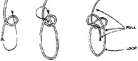
FIG. 5-9. BOWLINE
· square knot - This
knot is used to join two ropes together. (Fig. 5-10)
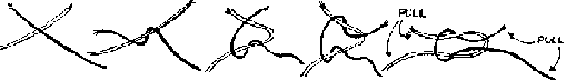
FIG. 5-10. SQUARE KNOT
· half hitch - This
is very commonly used to attach a rope around a solid object. Once tied, it is
difficult to tighten the rope although the knot itself will only become tighter
if the rope is pulled. (Fig. 5-11)
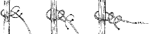
FIG. 5-11. HALF HITCHES
3. Buckets
The use of two or three different kinds of buckets is often
convenient for work in a well.
To avoid the possibility of tipping over while being lowered or
raised in the well buckets should have two features (Fig. 5-12).
· handles attached
to the bucket along its upper rim. Any weight in the bucket will tend to keep it
upright.
· buckets should be
deeper than wide, which concentrates the weight further down making the buckets
even harder to tip over.

FIG. 5-12. BUCKET
Buckets, like ropes, should be checked regularly for defects.
Particularly look for:
· a weak
bottom;
· a worn handle/bucket
junction;
· cracks or broken
places;
· worn handle.
Discard rejected buckets, if possible, to avoid possible future
confusion and unsafe use in the well.
Buckets may be used for different operations and their desired
features will vary accordingly. Buckets used in excavation, such as removing
soil and rock from the hole should have:
· handles that
connect to the bucket rim;
· greater depth
than width;
· reinforced bottoms;
· handle safety latches; and
· hooks in the middle of the handles.
Buckets used for cementing (lowering cement into the well)
should have:
· handles connecting
to the rim of the bucket;
· wide rims for
pouring.
Buckets used for lowering and raising tools should have:
· handles connecting
to the rim of the bucket;
· greater depth
than width.
4. Pulley
The use of a pulley will greatly facilitate well construction
work. If unavailable, arrange a cross piece with a smooth surface over which you
can pull the rope. It is far more preferable to pull the rope over a pulley than
try to stand at the well edge and pull the rope straight up hand over hand.
Ropes will wear much faster when pulled over even a relatively smooth surface
than when a pulley is used and should therefore be checked frequently.
· Pulleys are often
available as a unit with a hook. (Fig. 5-13)
· Pulleys can also be built with shaft ends. (Fig.
5-14)
· Pulleys may be mounted in hard wood
blocks anchored to solid frame. (Fig. 5-15)
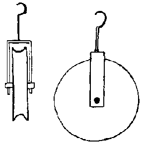
FIG. 5-13. PULLEY WITH MOUNTING HOOK
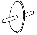
FIG. 5-14. PULLEY ON A SHAFT
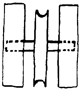
FIG. 5-15. PULLEY MOUNTED IN WOODEN
BLOCKS
5. Brake Post
The brake post is a log set in the ground 4 to 5 m from the well
which, when the raising/lowering rope is wrapped around it several times, acts
as a friction brake. This can help, especially when lowering heavy objects into
the well, by allowing much easier control of the lowering speed. A person
standing behind the brake post controls the lowering speed by the amount of
tension he/she keeps on the rope as it feeds around the post and on to the well.
A brake post should be:
· located 4 to 5 m
from the well straight out from the pulley (See Fig. 5-1.);
· about 25 cm in diameter, round, and smooth;
· set in concrete 1 m into the ground;
· set at an angle of about 60° from the
well.
Chapter 6: Digging
A. Introduction
Hand dug wells are sunk working down inside the hole to loosen
the sub-soil which is then lifted to ground level and dumped. How one actually
digs and then lifts out the loose dirt and rock depends largely on personal
preference, based on the available equipment and safety procedures one wishes to
follow.
B. Tools
The tools you need depend on the soil conditions. Shovels, pick*
mining bars, hoes, jack hammers, and hands have all been used. Anything that
will loosen the dirt and rock so that you can then load it into containers and
haul it to the surface will work.
NOTE: By shortening the normally long handles of shovels in
particular, you can reduce the possibility of injuries and make them easier to
use in the confined space at the bottom of a well.
C. Digging
Digging a hole that reaches water and becomes a well is slightly
different from just digging a hole. Pay attention to the diameter of the hole,
how smooth and even the walls are, and whether the hole is straight up and down.
Many people have found it convenient to follow these steps when
using a sinking technique where the hole is first dug, and lined afterward.
· Dig down and
remove a layer from 10 to 40cm thick that comes to within 5 or 10cm of the
desired diameter (see Fig. 6-1b);
· Continue removing
layers of soil until you have reached a depth of about a meter (see Fig.
6-1c);

FIG. 6-1. STEPS TO DIGGING THE HOLE
· Now go back and
trim out this section to the desired diameter, making sure that the hole walls
continue to be plumb (see Fig. 6-ld);
· Continue this
process, which may be broken up by periods of lining the hole, until you reach
the desired depth of the hole.
While digging a well, you are likely to encounter several
different types of soils which range between very loose and very hard. It can be
difficult to sink a hole into either extreme. Digging in loose, dry sand can
present some serious problems because of its tendency to fall back in. Dry sand
acts like a very thick liquid. Unless you can stop the sand from continually
flowing back, your well will end up V-shaped but even wider at the top than the
hole is deep. In such a situation you can sometimes stop the sand by digging 10
to 15 cm and then splashing a mixture of cement and water on the wall. This will
dry in minutes to form a thin hard layer. If that fails, pour 200 liters of
water into the hole before digging the next meter. This saturates the sand to
make it more stable. If this fails, you should consider sinking the lining
through the sand.
D. Hard Rock
Digging down and reaching a hard rock layer above an aquifer is
one of the most discouraging things that can happen to a well digger, who must
then either fry to continue sinking the well into and through the rock layer by
whatever means possible, or abandon the hole and try again someplace else.
In order to proceed correctly you need to research and analyze
existing information on water a:cessibi]ity and rock layers. Often there will be
only minim documentation available. Wells project workers may have to reach
conclusions on the basis of incomplete information. Here is a series of
questions, the answers to which will assist well workers in developing such
information:
· Has this or a
similar rock layer been encountered before in other attempts to sink
wells?
· Where were the wells
attempted?
· At what depth was rock
encountered?
· Is this a situation that local
people know about?
· Is this a general long
slope of the ground surface in a certain direction?
· What do you think happens to this rock layer in that
direction?
· Is there another source of water
that could be further developed to supply additional water?
· How important is it that these people have a well to
supply them with water?
E. Plumb
An object is plumb if it is straight up and down (perfectly
vertical). Wells should be as plumb as possible for convenience and to avoid
many other possible complications. This is particularly important in sinking
pre-cast lining sections. Structurally, a well that is plumb is generally
stronger than one that is not.
Plumb can be checked with simply a string with a weight tied to
the bottom of it (see Fig. 6-2). Plumb-bobs can be purchased commercially and
are relatively cheap. For convenience sake it may be useful to purchase one,
especially if there is a sliding piece for the top which is exactly the same
width as the plumb-bob itself so that you can easily get exact measures.
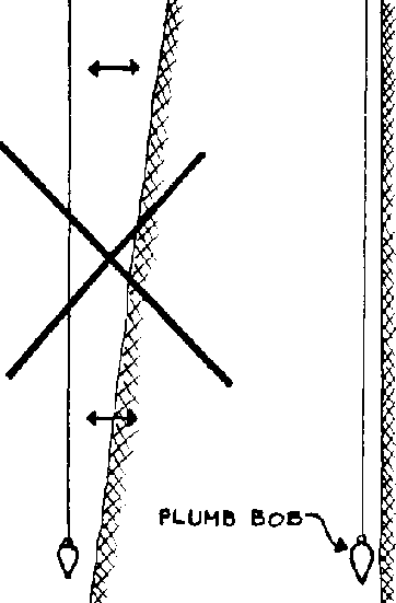
FIG. 6-2. PLUMB-BOB BEING USED TO
CHECK PLUMB OH HOLE
F. Diameter
It will be necessary to regularly check the diameter of the well
for many reasons. The hole you dig should have the exact diameter that you have
designed for it.
If the hole diameter is lest than planned, the precast lining
may not fit or poured concrete walls, will be thin and weak. This can be easily
fixed by trimming the hole to the desired diameter.
If, on the other hand, you have dug the hole too wide, it
probably won't affect the final condition of the well, but you will have spent
unnecessary extra time digging and it will take more time, and perhaps
materials, to fill the well back in to the desired diameter. Excessive width is
especially serious when pouring concrete walls in place in the well. The
diameter of the forms is set and filling in behind them will require a great
deal more concrete.
G. Methods of Checking the Diameter
1. Drop Bar
Preparation
· Bend 6mm re-rod
into a circle which conforms to desired circumference of the well.
· Continue bending
the re-rod around a second time to make double bar and tie the two
together.
· Check roundness by
rotating a straight bar the same length as the diameter within the circle drop
bar.
During Digging
· Dig one meter and
be careful not to displace the drop bar or excessively dig outward at the wall.
After you have dug one meter, you are ready to use the dropbar.
· For right-handers,
place your left hand lightly on the bar. Hold the trowel sideways under your
left forearm. Using the upper back corner of the trowel, work towards your body
and scrape away the dirt below the bar.
· Work along the
circumference, scraping away just enough dirt to allow the bar to drop. Continue
in this manner, working around the hole until the bar is at the bottom of the
hole.(see Fig. 6-3.)
· If you constantly
look at the bar and keep it level, the bore of the well will be straight and
consistent.
· If you now plan to
pour the lining in the well, dig a bit with the trowel until the bar is below
the floor of the first dig and cover it with sand.
· Do not smooth the
wall.

FIG. 6-3
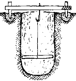
FIG. 6-4

FIG. 6-5

FIG. 6-6
2. Other Methods
This next method can be used to check both the diameter and
plumb and can also be used to center forms used in the well.
This method involves hanging a measuring bar from the center of
a centering board which fits across the top of the well and is located by a
stake on either side of the well. (See Fig. 6-4.)
· Dig anchoring
holes for re-rod stakes, one on either side of the location of the well and
about 30cm back from what will be the edge of the hole.
· Cement stakes in
place and place tops of both stakes through holes already drilled in centering
board before the cement sets, to exactly locate stakes.
· Locate a hook or
hole in the center of the board
· Draw a circle of
the desired hole size in the ground centered at the hook. This exactly locates
the hole to be dug.
· As each meter is
dug, hang the measuring bar from a line board over the hook. The bar should
pivot freely, just touching the edge of the hole with both ends to indicated
that the hole is both plumb and the proper size.
A variation of this would be to use a plumb-bob to locate the
center and gauge the radius of the well from there. (See Fig. 6-5) Hang a
plumb-bob from the hook to locate the center of the hole.
· With a re-rod
measuring piece cut to the exact radius of the hole, check the diameter as shown
in Fig. 6-5. The measuring piece should just fit between the plumbline and the
wall.
A person could also stand in the hole with a rod which is the
exact diameter as the hole in order to trim the hole down to the desired size.
(See Fig.
6-6.)
Chapter 7: The middle section: overview of lining techniques
A. Introduction
The middle section of the well is the first part to be built. It
involves digging and lining the hole from the ground surface to the water table.
B. Lining: Purposes
The lining is a circular wall made of a strong, permanent
material placed or built adjacent to the walls of the hole.
The lining has three purposes:
· it retains the
walls after completion; it keeps the hole from caving in;
· it acts as a seal to prevent polluted surface water
from entering the well;
· it serves as
foundation and support for the well top.
Wells should be lined if possible. Without linings, wells are
subject to damaging cave-ins.
Only in hard rock formations are linings not necessary because
rock is not liable to cave-in. Linings should be built of permanent materials
which will not rot, decay or otherwise lose their strength in a relatively short
period of time.
In some places wells are lined, meter by meter, only down to a
depth of about 3 meters. From there down the walls are left unlined. Such a
limited lining reinforces what is normally the most unstable part of the well.
If caving in is not a problem, this amount of wall reinforcement may enable the
development of a semi-permanent water source. It requires a minimum amount of
materials but is not really suitable for development as a sanitary water source.
It would be tempting to think of this kind of well as an
appropriate temporary solution which could later be easily up-graded to meet the
need for a permanent sanitary water source. However, consider that although the
partlylined well meets the current water needs, it may be difficult to motivate
local inhabitants to donate time and money to later improve a source that
already meets their felt needs.
Lining: Methods
There are two basic methods of lining a hand-dug well.
· Dig and
line
The hole or a portion of the hole is first dug and then lined.
This is a very flexible method and is therefore suitable for use in many
different ground conditions.
· Sink
lining
Pre-made lining sections are put in place and sunk by digging
soil out from inside the bottom lining section. This method is used primarily in
loose, dry sands where dig-and-line methods will not work because hole walls
cave in too quickly.(Fig. 7-1)
1. Dig and Line
This method,which has been traditionally used for well sinking
in all parts of the world,has many variations that make it suitable for many
different construction materials and ground conditions.
In this method the hole is always dug first and then lined.
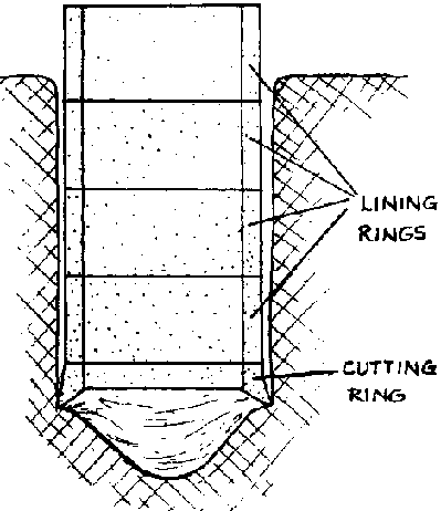
FIG. 7-1.
Commonly used variations of this method are:
· dig-a-meter,
pour-a-meter (see Fig. 7-2);
·
dig-and-line-in-short-sections(see Fig. 7-3);
· dig a hole to water and line;
· dig a hole as far into water as possible and
line.
The advantages of a dig-and-line method are that:
· it enables you to
dig as deep as you can before committing expensive materials to lining the
hole;
· it is capable of
penetrating anything except hard rock (hard rock can sometimes even be
penetrated for short distances);
· the lining can be
built in place in the well or built on the surface and lowered into the
completed hole;
· the lining curbs
(see p. 69) can be built in to increase lining stability.
Its disadvantages include:
· possible dangers
from cave-ins if the hole is dug too far without lining;
· requiring more work in the well than
"sink-lining."
2. Sink Lining (Caissoning)
This method is most suitable for use in loose fluid soils.
The lining is assembled at the surface before it is sunk. It can
be made of pre-cast reinforced concrete rings which are set in place at the
ground surface one by one as the others are sunk, or brick or circular rock
walls which are built up at the surface layer by layer as the column sinks.
The lining is sunk by workers standing inside the lining column
and digging out soil. As more supporting soil is removed the lining will
gradually sink under its own weight.
The sinking proceeds by digging out soil until the top of the
lining sinks almost to ground level and adding another lining section, digging
and sinking that section to the ground level, and so on until the lining is sunk
as far into the water as possible.
FIG. 1-2. DIG-A-METER, POUR-A-METER
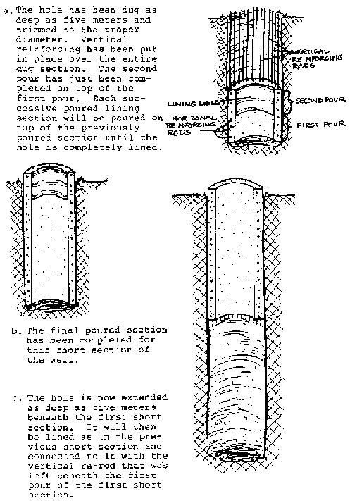
FIG. 7-3.
DIG-AND-LINE-IN-SHORT-SECTIONS
As a well sinking method to be used from the ground surface,it
is useful for shallow wells and those wells with larger than normal diameters
where the ground in free from boulders and other huge obstructions.
This method has these advantages:
· the equipment is
simpler than that required for dig and line;
· a headframe is not essential;
· not as much re-rod is required;
· most construction work is carried out on the
surface;
· advance preparation of lining can
significantly speed the sinking process.
The disadvantages include the following:
· it is difficult to
keep shaft vertical;
· boulders or even large stones
in the ground can cause the column to tilt;
· the stability of the completed
lining depends entirely on the friction between the lining and the hole wall and
since this is irregular, stresses are set up which may cause slipping, jamming
or opening construction joints;
· as the depth of
the well increases, a tendency develops for sections to "hang", causing tension
failure, or to buckle or crush under the weight of the column of
rings;
· the aquifer may
become contaminated by seepage from the surface down the outside of the lining
ring because it is not sufficiently form-fitted to the hole wall.
D. The Curb
The curb is an elbowshaped cut made in the wall that is poured
full of concrete and acts as an anchor to prevent the lining from sliding down
through the ground. The bottom of the cut is flat, 40 cm into the wall, and the
top is cut 40 cm higher than the bottom cut, and allows concrete to flow to all
parts of the curb. The rerod should be attached to each vertical(as shown in
Fig. 74). It will obviously take more concrete for a pour that includes a curb.
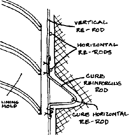
FIG. 7-4. LINING CURB
There is no commonly accepted standard regarding a recommended
distance between curbs. In fact, some sources question whether they are even
necessary where a concrete lining is poured in place. Other sources recommend
curbs every 5 meters to 10 meters. It is recommended here that curbs be
installed every 10 meters.
It is always a good idea to install a curb at or near the bottom
of the middle section lining, just above the water table.
E. Cast-in-Place Versus Pre-Cast
1. Definitions
Cast-in-Place
The lining is built in place right up against the walls of the
hole.
Pre-Cast
Sections of the lining are built above ground and later lowered
or sunk into place in the well.
2. Decide Whether to Pre-Cast or Cast in Place
The decision to pre-cast or cast in-place the middle section
lining usually depends on such factors as size of the project, lining materials,
equipment available, ground conditions, and personal preference.
Generally, a lining that is built in place is better than one
that is built ahead of time and then installed in the well. By building it in
place, especially if using reinforced concrete or mortar, the lining conforms to
the walls better, providing greater adhesion, stability, and sealing, as well as
preventing the entry of contaminated surface water.
|
Cast-in-Place |
Pre-Cast |
|
· generally preferable - strong,
waterproof, permanent; |
· e forms helpful but not
required; |
|
· bonds well with ex- cavation
walls; |
· pre-made concrete sections
available. |
|
· limited working space |
· provides more time in the well
and space to build a stronger lining; |
|
· may not bond well with the
hole wall; |
|
· requires heavy lowering
equipment. |
To prevent tools and materials from being accidentally knocked
into the well and the possible collapse of the looser surface soil into the well
you may wish to install a lining in the top meter of the well as soon as it is
dug. This can be either a temporary or permanent lining depending on what
materials you have available and the lining method you plan to use.
When in place, this lining should reach at least 10 cm above the
ground surface to prevent tools, materials, and other articles from falling into
the well.
An inside lining mold can be used as a temporary lining. (See
Fig. 7-5.) There must be enough room for people and supplies to move in and out
of the hole. The mold should be carefully packed in place to prevent it from
slipping down while the hole is being excavated beneath it. Remember that, once
in place, this temporary lining cannot be moved until the construction is
complete. It is, therefore, necessary to plan on making or purchasing this in
addition to all lining molds needed for the construction of the permanent
lining.
If you build a permanent lining, pour it in place possibly with
an anchor above ground.
As you sink the well beyond this top support, taper the inside
hole walls out to the desired hole diameter about 30-40cm below bottom of top
support. This will help support it while digging continues below it.
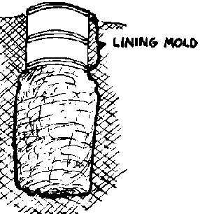
FIG. 7-5 LINING MOLD AS TEMPORARY
LINING
If you decide not to put a top support in you should make some
effort to ensure that workers in the well are safe from ground surface collapse
and accidental entry of anything into the well. For example, four boards may be
laid in a square around the hole and used to accomplish this.
Such a construction will help to distribute weight near the edge
of the hole and act as a constant reminder to well workers and others to be
careful.
Many wells have been dug without the use of any measures to
prevent accidents except to warn everyone about the consequences. Well workers
will all be sensitive to the need for safety but local villagers often are not.
In some cases wells projects have established rules that no one,
including village elders and children, can come within 2 meters of the well
until it is completed. This may be hard to enforce but is nevertheless a very
useful procedure.
NOTE: Hole diameter and lining thickness: As a general rule the
lining thickness should be about 1/20 of the hole diameter but never less than 7
cm.
Finish well diameter = interior lining form diameter = 9/10 hole
diameter (for wells w/hole diem. 2 1.40m)
F. Lining: Materials
The availability of material. largely determines how you line
the well. Here are the most frequently used lining materials in order of
preference.
This order is generally applicable to most locales although
there may be minor changes due to limitations of geological conditions. Such
limitations are almost always due to the fact that soil conditions will not
permit you to dig down to the water table without first reinforcing the walls.
The installation of temporary reinforcing is sometimes an appropriate solution,
but that involves a large added expense for temporary lining which is beyond the
scope of this manual.
· Reinforced
concrete
This is probably the best material now commonly available for
large-diameter well lining. When properly cured it is very strong. Depending on
its ingredients it can be virtually waterproof or quite porous. Re-rod is
available in most countries, although it is sometimes difficult to transport to
the well site. Concrete can be precast into appropriately sized sections and
then lowered into the hole or it can be poured and cured in place inside the
well. Depending on what other equipment and materials are available for use with
it, it is the most adaptable material for many of the situations which may be
encountered in wells construction.
· Reinforced
mortar
This material has all the same advantages and uses as reinforced
concrete. The difference is that only sand is added to cement to make mortar
while sand and gravel are added to cement to make concrete. Gravel acts as a
stretcher to make the concrete go further so mortar is more expensive for the
same volume of final product. Mortar is a more "workable" mixture and in some
cases may be more suitable than concrete.
·
Concrete
Concrete without re-rod is not as strong as reinforced concrete.
·
Mortar
This has the same qualities as concrete but is more expensive.
· Brick
Brick should be solid rather than hollow. It is best suited for
digging to the water table and then lining the complete well. It can be used to
line in short sections although it is difficult to support a lined section while
digging beneath it. Mortared brick makes a strong lining but does not adhere
very well to the hole wall.
· Rock
Rock is very similar to brick in that it is best suited for
lining a hole that has been completely dug. Mortared rock walls can be quite
strong although because of their irregular shapes and strengths they will often
contain weak spots and be subject to cracking.
Unmortared rock walls can also be very strong if built properly,
but require proper materials and a degree of expertise which cannot be
adequately covered in this manual.

FIG. 7-6. ROCK WALL
· Timber
(wood)
The only advantages of wood are that it has been generally
available, moderately strong and cheap. In many areas of the world wood is no
longer generally available or cheap, and its disadvantages are such as to
prevent any serious consideration of wood as a lining material for a permanent
potable water source. It is liable to rot, taint the water and harbor insects.
It is impossible to make the lining watertight and so prevent re-entry of
contaminated surface water.
G. Possible Digging/Lining Methods for Each Material
1. Reinforced concrete cast in place:
· Dig to water and
line;
· Dig-a-meter, pour-a-meter;
· Dig and line in short sections.
2. Reinforced concrete pre-cast:
This requires heavier capacity lowering equipment.
· Dig to water and
line;
· Sink lining.
3. Reinforced mortar thrown in place:
· Dig to water and
line;
· Dig-a-meter, pour-a-meter;
· Dig and line short sections.
4. Reinforced mortar pre-cast:
· Dig to water and
line;
· Sink lining.
5. Unreinforced concrete or mortar cast in place:
This has very little tensile strength.
· Dig to water and
line;
· Dig-a-meter, pour-a-meter;
· Dig and line in short sections.
6. Unreinforced concrete or mortar pre-cast:
Its low tensile strength makes lowering it into the well
difficult,
· Dig to water and
line;
· Sink lining.
7. Brick or rock:
These materials also have relatively low tensile strength:
· Sink lining (on
cutting ring);
· Dig to water and
line;
· Dig and line in short sections with
anchoring curbs.
8. Wood (timber or split bamboo):
· Employ verticals
with horizontal supports all anchored to walls;
· Use any sinking method but try to avoid the use of
wood in the first place, for reasons discussed above.
NOTE: Efficient use of cement
Cement is probably the most expensive material of all so it
should be used as efficiently as possible.
Of all cement compounds, reinforced concrete requires the least
amount of cement per volume of building material (either mortar or concrete)
produced.
On one wells construction project where 50 cm rock walls were
built, 15 cm reirforced concrete was tried instead.
The results were a 1/3 reduction in cement used, walls were more
waterproof, and the construction time was significantly reduced. The initial
cost was greater because of the need for forming materials, but forms can be
re-used. By prorating the cost of forms over a number of wells and figuring the
reduced labor costs the total cost of each well went down about
25%.
Chapter 8: Construction of the middle section
A. Introduction
This chapter first presents a step-by-step description of the
use of reinforced concrete in the construction of the middle section by three
methods: 1) dig-a-meter, pour-ameter; 2) dig-and-line-in-short-sections; and 3)
dig-to-thewater table-and-line. It then describes the use of the same material
in building lining rings and concludes with a discussion of the use of
alternative materials, mortar and mortared brick or stone.
B. Sinking Depth and Lining
How deep you sink the hole before you begin lining it is a
question you must answer for yourself,given the local conditions. Major concerns
are the ground conditions, the lining material to be used and personal
preference.
· ground
conditions
In loose soil, dig to whatever depth can be conveniently dug and
lined without the hole walls caving in; 1/2 meter is the usual minimum.
In firm soil, the maximum recommended depth without lining is 5
meters. This is usually a safe depth and may prevent or at least limit the
damage resulting from caveins.
Many experienced well diggers will simply dig as far as they can
until either 1) walls show signs of loosening and possible cave-in, or 2) they
reach the water table. This is, however, not recommended for beginning well
diggers who have little or no experience estimating the strength of various
ground formations.
NOTE: In some locales where the soil is firm all the way down to
the water table, entire wells have been dug before any lining was constructed.
Where necessary and where ground conditions permit, wells can still be dug that
way.
C. Dig-a-Meter, Pour-a-Meter
One meter is the height of the circular forms, sometimes called
molds, which will be placed in the well and around which concrete will be
poured. Circular lining forms do not have to be one meter high and where they
are not the general procedure for this digging/lining method can still be
followed. Another name for this method could be dig one mold height and then
line one mold height.
· Outline of
Work
1. Dig the hole to the specified depth.
- Check the diameter and plumb.(See pp. 59-62.)
2. Assemble the re-rod cage in place.(See Fig. 8-1.)
- 25 to 30 cm of each vertical re-rod should extend into the
soil below the bottom of this pour.
- Evenly space the horizontal re-rods along the height of the
pour and tie them to the verticals.
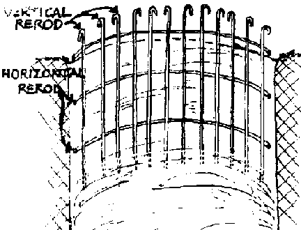
FIG. 8-1. REINFORCED CONCRETE LINING
BUILT IN PLACE (a)
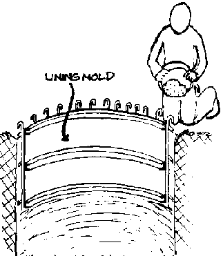
FIG. 8-1. REINFORCED CONCRETE LINING
BUILT IN PLACE (b)
a. The hole has been dug to the required depth and rerod
verticals stuck into the ground. The rerod horizontals are then tied to the
verticals.
b. The inside lining mold has been centered and leveled.
Concrete can now be poured around the rerod between the lining mold and the side
of the hole. Also see Fig. 83.
3. Lower and assemble the mold.
- Level and center the mold. This is very important for the
first section.
4. Pour concrete behind the mold (see Fig. 8-lb) and on all
sides of mold to evenly distribute and not displace the mold. Gently tap around
mold with a hammer to settle the concrete and prevent honeycombing.
5. Leave the mold of first pour in place
- Dig beneath it to a depth of a mold plus 10 cm (815 cm) (If 1
m mold, dig 1.1 m; if 1/2 m mold, dig 60 cm)
- Check diameter and plumb.
6. Assemble the re-rod in place.
- Tie the top of the
vertical piece to the bottoms of the pieces extending out below the previous
pour.
7. Lower and assemble the mold (another one, or the drop mold
used in the first section)
- Level and center the mold.
- There will be a 10 cm gap between the top of the mold and the
bottom of the previous pour through which to pour the concrete.
8. Mix and pour the concrete behind the mold.
9. Continue as in second meter.
After the mold is placed for the third pour, plaster the joint
between the first and second pours with mortar for a smooth continued surface.
A more specific work plan for each of these steps is given in
the next section.
· Dig-a-Meter,
Pour-a-Meter: Work Plan
1. Dig hole to desired depth
- Check diameter and plumb. (See pp. 59-62.)
- Determine depth of hole, as follows.
When you dig the hole for the first one meter section to be
poured,the actual depth of the hole will depend on 1) how much of a headwall you
wish to include as part of the first pour, and 2) how you can best leave 25 cm
to 30 cm of each vertical re-rod beneath the pour in such a way that they will
not be embedded in the concrete. This will later be connected to the next lower
pour.
Here are various headwall options for your consideration:
- No headwall
The depth of the hole is the height of the mold so that the pour
will be flush with the ground surface. (See Fig. 8-2.)
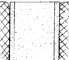
FIG. 8-2. NO HEADWALL
- 10 cm headwall
The depth will be 10 cm less than the height of the mold.
- 50m headwall
You will need an optional 50 cm exterior headwall mold. The
depth will be 50 cm less than the height of the mold. For a 50 cm headwall the
mold should be 1m high. Assemble the normal 1m re-rod cage in place. The cage
will extend almost 50 cm above ground. Place, level and center the interior and
exterior molds. The tops of both molds should be approximately even with the top
of the re-rod slightly (3 cm) below that. The width of the headwall is
determined in the same way as the hole diameter.
2. Assemble re-rod cage in place.
The total height of the vertical re-rods should be (mold height)
+ 20(re-rod diameter)+ 10 cm (for space to pour concrete between pours) + 10 cm
(for one 5 cm hook on each end of the rod).
For example: When using a one meter mold and 8 mm re-rod
verticals will be 1 meter (mold height) plus 0.16m (20x8mm re-rod diameter) also
.10m (for concrete pouring gap) plus .10m (2-5 cm hooks). The verticals will be
1.36 meters long.
- Normally use about 15 vertical pieces although you may need up
to 30 pieces in very loose unstable soil.
- Bend over a 5 cm hook on one end of each vertical re-rod.
- Space re-rods evenly around the hole. Push the unbent end of
each re-rod about 30 cm into the ground or until the top of the hooked end is
about 3 cm below the top of this poured section of lining.
- These re-rods should all be pushed into the ground where they
will be approximately in the middle of the lining thickness. (See Fig. 8-3)

FIG. 8-3. PLACEMENT OF RE-ROD AND
FORM IN HOLE
- If the ground is too hard to push the re-rod straight down,
then dig down far enough to provide space for the bottom ends and fill the hole
back in to the desired depth. However, this may waste time and effort that could
be used more economically by digging the hole deeper before you line it. (See an
alternative sinking technique on p. 86.)
- You will normally need 3 horizontal reinforcing rods per
meter, although in loose soil 4 horizontal re-rods are better. These will be
circles of re-rod with a diameter slightly less than the hole, they are usually
placed on the outside of the verticals.
- To compute the length of re-rod which will need to be bent
into the proper size circle for use as a horizontal reinforcing rod, used the
following formula. The complete lengths of the re-rod will be the distance
around the circle at the point where the re-rod will be placed, plus the length
of the re-rod overlap, plus the length of the hook on each end of the re-rod.
[( hole diameter) -(lining thickness)] x 3.1416 + 20(re-rod
diameter) + 2(5cm end hooks = length of horizontal re-rod
Example: For a well with a hole diameter of 1.5 meters with a
lining thickness of 7.5cm (.075m) using 6mm (.006m) re-rod, the computation
would look like this.
[(1.5) - (.075)] x 3.1416 + 20 (.006) + 2 (.05)
[1.425] x
3.1416 + 0.12 + 0.10
4.48 + 0.12 + 0.10 = 4.7 meters.
- Horizontals should be evenly spaced in each meter; for
example, if there are three horizontals, one is placed in the middle of each
meter; the other two are placed 37cm away on either side. (See Fig. 8-3) Be sure
to include the 10cm or 15cm gap between successive poured sections if applicable
in the computation of the length over which the horizontal re-rods should be
evenly spaced. Tie all intersections of horizontal and verticals; make sure the
re-rod is no closer than 3cm to the hole wall. Put pieces of stone or dried
concrete between the rerod and the hole wall where it is necessary to ensure
spacing.
NOTE: Instead of using a certain number of horizontal pieces,
you can also use a continuous spiral re-rod which circles the hole 3 or 4 times
per meter depending on how strong the lining must be.
3. Lower and assemble the mold.
- Lower the mold sections into the well and assemble them in
place.
- It is also possible to assemble the mold above the ground and
lower it into place.
- Center the mold in the hole making sure that it is level and
that the distance between the mold and the hole wall is the same all the way
around the hole. (See Fig. 8-4.)

FIG. 8-4. MOLD LEVELED AND CENTERED
- It is very important that the mold be correctly centered and
leveled for this first section because all of the other pours must line up and
be attached to it. If the first poured section is not aligned properly all
subsequent sections, if followed from the first one, could magnify that error
and cause the well shaft to curve or angle out of plumb as it is sunk.
- Especially with the first meter it is often a good idea to
check the level and centering again, just before the concrete is poured, to make
sure that it has not been disturbed.
4. Pour concrete behind mold.
- Concrete is mixed on the surface (See Cement Appendix, p.
221.) and lowered in buckets down to workers in the well who will pour the
concrete behind the mold.
- When pouring concrete behind the mold, do so from alternating
opposite sides of the mold. If you continually pour the concrete into one spot
or unknowingly concentrate on one side of the concrete, it will soon build up
enough weight that it will move the mold off center or out of line. Once that
happens it is virtually impossible to move the mold back to its intended
position. (See Fig. 8-5.)
- Once the concrete is poured, gently tap around the inside of
the mold with a hammer. This slightly vibrates the concrete so it settles into
any voids that may have been left while pouring. After the concrete has set in
an hour or two, you can begin working on the second pour.

FIG. 8-5. POURING CONCRETE EVENLY IN
PLACE AROUND MOLD.
5. Dig hole beneath the first poured section
The depth of this dig should be the mold height plus 10 cm for a
gap between the bottom of the first poured section and the top of the second
pour through which you will pour concrete. (See Fig. 8-6.)
FIG. 8-6. PROPER HOLE DEPTH BENEATH
AN ALREADY POURED LINING SECTION
6. Assemble reinforcing rod in place
Bend a 5 cm hook on the bottom ends of the re-rod extending down
from the previously poured section.
Place the horizontal pieces in the well; pull the horizontal
pieces up into place and tie all intersections with horizontals.
Assemble the same number of vertical pieces as in the first
pour.
Bend a 5 cm hook on one end; stick the unhooked end into the
ground 25-30 cm directly beneath the verticals of the previously poured section
and inside the horizontals lying on the ground,
Connect the verticals to the previous verticals with sufficient
overlap, twenty times the diameter of the rerod, and a 5 cm hook at either end
of the overlap.
Place the horizontals as in the first pour. Make sure the re-rod
is no closer than 3 cm to the hole wall.
7. Lower mold into place
If you have only one mold, remove and lower it from the
previously poured section.
This way it is possible to dig and line about 1 meter each day
in soil that is easily dug. A single mold should be cleaned and oiled at least
once every 3 meters,
During the one day that each poured concrete section sits while
the following section is dug, it will set sufficiently to enable the mold to be
carefully removed. (See Cement Appendix, p. 221.)
If you have more than one mold you may leave them in place until
needed for constructing subsequent sections.
Center and level (plumb) the mold.
8. Mix and pour concrete behind mold
Don't forget to alternate sides for pouring each successive
bucket to allow the concrete to settle evenly.
9. Successive pours
- Continue as in second pour;
- Fill gaps between pours with mortar when the molds have been
removed from both sections.
D. Dig-and-Line-in-Short-Sections
This lining method involves digging the hole to some convenient
depth and then lining it. Once the lining for that section is complete and is
anchored in place, continue digging the hole beneath the already lined sections.
These sections are dug and lined until the water table is reached. The depth of
each section can be whatever you feel comfortable with both from the point of
view of safety and work convenience.
1. Dig hole to certain depth
Dig a hole until you reach a depth where you feel it might be
unsafe to continue, or until you have sunk the hole a maximum of 5 meters.
Depending on whether you want a headwall and, if so, on the height you want it
to be, you may want to slightly change the hole depth so that the top of the
mold will be at the desired top of the headwall after a number of poured lining
sections are completed.
2. Assemble re-rod cage in place
- Where possible, use single long pieces of re-rod for
verticals. These can be anchored to the hole wall with short pieces of re-rod
bent into hooks and pounded into the hole wall around the verticals.
- Put horizontals in place, beginning at the bottom and working
up.
- Tie each horizontal in place temporarily with enough ties to
hold it in place. This allows for any adjustments that might be necessary later.
- Before the mold is put in place for each pour, securely tie
all of the intersections of horizontals and verticals.
3. Lower and assemble mold
- Level and center the mold in the bottom of the hole.
4. Pour concrete behind mold
- Leave the top surface rough for a good bond to the next pour.
5. Lower and assemble another mold
- Set it directly on top of previous mold;
- Pour concrete behind mold;
- Repeat this step until you reach the ground surface or bottom
of the previous set of pours.
6. Repeat steps 1 through 5
- Repeat these steps until water is reached. The bottom of the
lining should be constructed with a curb just above the water table.
NOTE: If you are digging and lining beneath a previous lift be
careful to leave enough room between the top of this lift and the bottom of the
previous lift through which YOU can pour concrete (See Fig. 8-6.)
E. Dig-down-to-Water-Table-and-Line
This method is recommended only where the water table is within
a few meters of the earth's surface and the ground is firm. It is included here
to demonstrate that the same operations must always be performed although,
depending on the depth, they may be done in a slightly different order:
1. The hole is dug down to just slightly above the water table,
2. Dig out a curb at the bottom of the hole.
3. Assemble the re-rod in place.
4. Set the form in place. Remember to carefully center and level
the form.
5. Mix and pour the concrete into the form.
6. Continue lowering molds on top of previous molds and pouring
concrete behind them until you reach the ground surface.
F. Pre-Cast Reinforced Concrete Rings
Pre-cast reinforced concrete rings are often used to line wells.
They are poured and cured above ground to be lowered into the well later. There
are two basic methods for installing rings:
· lowering and
stacking them in an already dug well: (See Fig. 8-7.)

FIG. 8-7. LOWERING PRE-CAST CONCRETE
RINGS
· setting them in
position at the ground surface and sinking them into place. (See Fig.
8-10.)
Rings should be made so that they:
· can be easily
stacked or attached one on top of another;
·
can form a watertight joint where they meet;
· are strong enough to support weight of a long column
of rings;
· will not rot, corrode, rust or
otherwise lose any of the above qualities;
·
will not react with water to make the water less desirable for
consumption.
This method is more useful in a large project where rings can be
centrally manufactured and then transported to the well site for use.
Making your own rings will require the use of inner, outer, top
and bottom forms. The inner, outer and top forms can be carefully removed after
the concrete has just started to set, usually in an hour or two, making it
possible to Make several rings each day if enough bottom forms are available.
Where a number of forms are available,it is better to leave them in place to
allow the concrete to cure better.
You can 1) make your own reinforced concrete rings or 2)
sometimes obtain them on the local market as culvert pipe or a similar item.
Both are suitable.
Determining how two rings fit together is a major concern when
lining a well with concrete rings. Frequently flat edges have simply been
mortared and stacked on flat edges. (See Fig. 8-8a.) This provides very little
resistance if an unequal sideways force is exerted. A tapered or flared fit is
better. (See Fig. 88b and c.) These will resist sideways forces better and
should be arranged so that water flowing down the outside of the lining will
tend to flow away from and not into the well. Where possible, the two rings
should be firmly attached together. This is most often done with nuts and bolts
through steel fittings cast into the rings. This type of connection is
especially useful when the lining will be sunk into place but may not be
necessary when stacking rings in an already open hole.

FIG. 8-8. CONCRETE LINING RING JOINTS
As with most other concrete casting techniques, the concrete in
the rings can either be made watertight or porous. Porous concrete rings can be
especially useful when sinking the lining into the bottom section of the well.
1. Stacked in open hole: Work Plan
- Dig curb slightly above water level;
- Reinforced the curb and pour it around a form in such a way
that a lining ring will sit on top of it. (See Fig. 8-9.)
2. Lower ring into place on top of curb.
- The major problem with lining a well this way is that there is
very little adhesion between the lining and surrounding soil.
3. Continue lowering rings and filling in around them until you
reach the ground surface.
NOTE: It may be useful to install curbs or some other type of
anchoring to help hoed the column in place.
FIG. 8-9. LINING RINGS LOWERED INTO
PLACE ON ANCHORING CURB
2. Sunk from ground surface: Work Plan
This involves stacking rings as necessary on a cutting ring
while the whole column is sunk by digging out soil from inside and underneath
the bottom of the column. Because of its complete protection from caving this
method is used in very loose soils that would be difficult to keep the column
going out of plumb, especially in loose soils. The problem is compounded by the
fact that once the column begins sinking askew it is very difficult and
sometimes impossible to get it straight again.
A cutting ring is a special ring that provides a cutting edge to
help sink the column and also helps to funnel soil directly underneath it into
the middle of the hole for removal. (See Fig. 8-lOa.)
1. Set 1 or 2 lining rings on top of the cutting ring. The more
rings you can stack, the more weight the column will have and the easier it will
be to sink. However, the rings are very heavy and it will usually be very
difficult to lift the rings any higher than 1 meter with locally made equipment.
2. Workers will stand inside the ring and dig to remove soil and
permit column to sink. (See Fig. 8-lOb.)
3. Digging should be done especially carefully to try to remove
soil evenly from around the bottom of the hole so that the column will sink
plumb.
4. Add more rings when the existing column sinks down to where
another ring can easily be added (usually about ground level or just above).
(See Fig. 8-lOc.)
5. Continue sinking the column and adding rings as far as
possible into the water table. (See Chapter 9, p. 99.)
NOTE: Because of the strong possibility of rings sinking askew
and the uneven forces that will often have to be applied to the column in order
to get it straight again, it is a good idea to have the rings firmly attached to
one another.
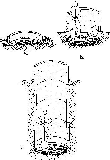
FIG. 8-10. SINKING LINING RINGS
Often in loose soil, mostly sands, the rings sink askew, which
causes problems, especially when the thickness of the loose layer is about 4 m
or mole. In less thick layers (about 2 m) the best way to sink the column
relatively plumb is to continue digging as fast as possible until firmer layers
are struck. Even if the rings are standing askew, they may be put in an upright
position again as follows.
If the rings are askew, as in Fig. 8-lla, work inside the column
of rings to remove the soil from beneath the lowest edge of the bottom ring as
shown. The hole you dig should extend underneath and beyond the outside edge of
the ring. When this is completed, carefully dig the soil away from beneath the
opposite side of the column but, on this side, try not to dig any further out
beneath the ring than absolutely necessary. (See Fig. 8-llb.) As the column
sinks from this point, it should gradually ease over toward the side that was
first dug out. (See fig. 8-llc.)

FIG. 8-11. STRAIGHTENING A COLUMN
THAT HAS BEEN SUNK OUT OF PLUMB
G. Mortar (plaster)
1. Cast in place
Reinforced mortar is used much like reinforced concrete. The
major advantage of this method is that no forms are required because the mortar
is thrown onto the wall in place.
This variation evolved in Senegal. It was difficult to transport
heavy steel molds to the well sites,so the masons would "throw" the concrete
onto the walls. But concrete is not very workable so the masons began leaving
out the gravel and using just mortar.
Walls are normally plastered meter-by-meter as the well is dug.
This is a variation of the "dig-ameter-poura-meter" method used with reinforced
concrete.
This process is as follows:
1. Dig the hole about 1.1 m deep.
2. Check the hole diameter and plumb.
3. Cut and shape as much re-rod as possible beforehand because
the next steps must be done quickly.
4. Splash the mixture (1:4, cement: water) on all surfaces to be
plastered. If the surface dries too quickly, wet it again immediately before
plastering.
5. Apply a 3cm thick layer of mortar with a trowel.
6. Place the re-rod.
7. Apply second 3cm coat of mortar while the first is still wet.
8. A third, thinner layer may be applied to make the walls as
smooth as possible.
2. Pre-Cast
Mortar can also be used to pre-cast rings even where forms are
not available.
1. Dig a round hole with the desired outside diameter of the
ring. (See Fig. 8-12a.)
- The hole's depth will determine the height of the ring.
2. The hole is then plastered and reinforced just as it would be
in the well. (See Fig. 8-12b and c.)
3. After it has cured for several days it can be dug up and
later installed in the well. (See Fig. 8-12d.)
- This type of ring should be allowed to harden for at least one
week before it is placed in the well.
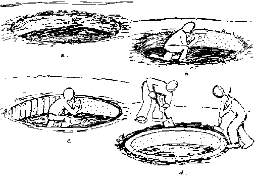
FIG. 8-12. CASTING CONCRETE RINGS IN
EARTH FORMS
H. Mortared brick or stone (masonry)
Rock has been used to construct linings in wells for centuries.
Construction of a well using rock usually involves digging the hole as far as
possible into the water table before the lining is built. Once the foundation
under water is established, the walls are usually built up in a double layer
about 50 cm. thick. Rock walls are very weak in tension so they can be easily
cracked if any uneven stresses are put on them.
This type of well can provide acceptable quality well water if
precautions are taken to prevent contamination from surface water seepage
through the lining. A 5 cm. thick layer of concrete or mortar around the top 3
m. of the lining can prevent the seepage of contaminated surface water back into
the well. In fact, the surface water seepage may eventually reach the water
table and find its way back into the well, but if this seepage has been filtered
through at least 3 m of soil, the potentially harmful contaminants will have
been removed. (See Fig. 813.)
Brick or stone masonry can be used in most of the different
digging and lining methods but, because of its tendency to crack under stress,
it is not normally used except to build the lining from the bottom of the well
up, in one continuous operation.
A brick or rock wall can be built up on a cutting ring and sunk
into the ground (See Fig. 8-14.) but any caving around the outside could crack
or topple the wall. If such a column were to sink askew it could be very
difficult to get it upright again without exerting some kind of sideways force
on the column which could crack or destroy the column.

FIG. 8-13. ROCK LINED WELL 3m OF
CONCRETE OR MORTAR SEAL IS TO PREVENT CONTAMINATION

FIG. 8-14. BRICK LINING SUCK ON A
CUTTING RING
It is possible to use reinforcing rod to help hold a brick
lining together. This is sometimes used in sinking the bottom section of a well.
It is not normally used for construction of the middle section because in most
cases a reinforced concrete or mortar wall could also be built with the same
materials, and provide a stronger lining. (See Fig. 815.)
It is also possible to use masonry to line the wall in sections.
When a lining is needed after having dug down a number of meters, a curb can be
installed and the lining built up on the curb. The curb serves as a base on
which the lining can be built up and as a solid anchoring piece which can be
supported to allow digging to continue beneath and through it As a safety
precaution, the curb should be supported by long pieces of wood, or whatever
else is available, which can be wedged between the bottom of the hole and the
curb. (See Fig. 8-and the curb. (See Fig. 8-16.)
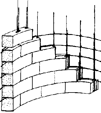
FIG. 8-15. REINFORCED BRICK LINING
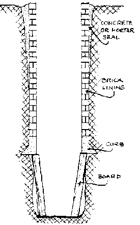
FIG. 8-16. SECTION OF BRICK
LINING
Chapter 9: Construction of the bottom section
A. Introduction
This chapter provides detailed information to assist wells
workers to construct the bottom section of the well. Describing the unique
features of that section, it also raises such special concerns as the choice of
sinking/ lining methods, selection of materials, keeping water out of the well
to allow diggers to dig deeper, and facilitating water entry.
The bottom section is that portion of a well below the water
table. Its purpose is to allow as much water as possible to enter the well while
blocking fine soil particles from the surrounding aquifer. This is accomplished
by digging a hole and extending an appropriate lining as far beneath the water
table into the aquifer as possible.
As the bottom section is being sunk, using whatever method,
water will have to be removed to allow continued sinking. This can be done by
simply filling the buckets normally used to remove excavated material and
emptying them at the ground surface, or by using a pump. Pumps are generally
easier to use because they allow water to be removed from the well faster; a
well can be dug deeper than if buckets were used. This will be especially
important if the bottom section is being constructed when the water table is
above its lowest level and the well is being finished at any other time than the
end of the dry season. (See Fig. 91.)
The construction of the bottom section consists or the same two
operations,digging and lining,as the middle section. However, because water is
entering the well while the digging is proceeding and the lining is being
installed, the whole process becomes more complicated.
These two situations will limit your ability to dig deeper:
· water flowing into
the well
As you begin to get into the water layer there will probably be
little water entering the well. As you go further down,water will enter the well
faster until 1) it is coming in so fast that you can no longer remove enough of
it to be able to continue digging or 2) you reach the bottom of the water
bearing layer. If you reach the bottom of the water bearing layer you will have
to evaluate whether the supply of water is sufficient for the needs of the local
users. Again there are two possibilities: a) the water flows very slowly,or b)
this is an isolated small pocket of water that is limited and will be quickly
used up.

FIG. 9-1. USING A PUMP TO REMOVE
WATER FROM BOTTOM SECTION WHILE SINKING
In a), the well will always have water in it but there may be
very little and people's water consumption may be limited. It might be possible
to dig other wells which could each supply a limited amount of water but which
combined with the rest would allow for an increase in water consumption.
In b), the decision will have to be made whether to try to
continue sinking this well or start another well in a different location.
· walls collapsing
as you dig
This is likely to be a problem in all wells, but it will be much
more serious in wells which reach aquifers composed of loose, usually sandy
soil. The deeper the hole is sunk into the aquifer, the more serious the problem
will become. The collapsing of the walls is caused mainly by the flow of water
coming into the well. The water, as it flows into the well, exerts pressure on
the aquifer particles around which it must pass. The faster the water enters the
well, the more pressure it exerts and therefore the more likely the walls are to
collapse. By sinking the bottom section lining ring into place, the possible
hindrance and danger of collapsing hole walls can be prevented. (See Fig. 9-2.)
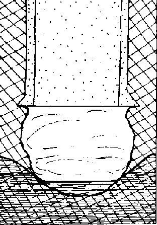
FIG. 9-2. HOLE WALLS COLLAPSING IN
BOTTOM SECTION
B. Sinking/Lining Methods
1. Sink Lining
To sink the lining into the bottom section the rings must be
made just small enough to fit inside the middle section lining. When using
reinforced concrete a different set of forms from those used for the middle
section lining will be needed. A well can probably be sunk a little deeper using
this method rather than others,because it allows workers to spend all their time
removing soil and water from the bottom of the hole,thus deepening it.
2. Dig-to-Bottom-and-Line
This method is limited to sites where ground conditions permit
digging below the water table. This can only be done where aquifers are made up
of relatively consolidated material and is not recommended where the aquifer
consists of loose materials that tend to cave-in.
NOTE: Wells have been sunk into loose, unconsolidated aquifers
by using temporary lining to reinforce the walls and prevent cave-ins. In most
cases today time and money that would before have been spent on temporary lining
can now be more usefully and safely spent working with permanent cement linings
installed as the hole is dug either by sinking the lining or digging and lining
in short sections.
3. Dig-and-Line-Short-Sections
It may be possible in slightly caving formations to dig and line
several short 1/2 m sections before reaching a point where water enters the hole
fast enough to slowly erode the earth walls or wash away wet concrete or mortar
from inside a form. At this point the fining can no longer be built in complete
rings but will have to be continued by completing each 1/2 meter ring in several
sections one at a time. The use of quick drying cement will significantly aid
this work.
Some have used this technique because it requires less
preparation than sinking a lining which requires pre-casting lining rings. It
requires less equipment and may produce a structurally superior well,although
the structural continuity achieved here may not be of significant advantage in
the overall functioning of a well. On the other hand, for shallow wells that
reach a limited supply of water, expenditure in time and money on a more
elaborate well structure probably will not be worthwhile. Also, the actual work
required is somewhat complicated, requiring well diggers to perform various
tasks simultaneously and with great competence.
C. Water Entry
The bottom section should tee constructed so that the water
comes in through the bottom, and perhaps lining, depending on the bottom lining
procedure and the ground conditions. (See Fig. 9-3.)
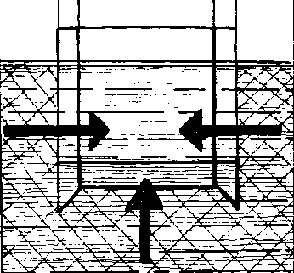
FIG. 9-3. WATER ENTRY INTO BOTTOM
SECTION
|
Lining Procedure: |
Water entry through: |
|
sink lining |
bottom, and perhaps lining |
|
dig-to-bottom-and-line |
bottom, and perhaps lining |
|
dig-and-line-short-sections |
bottom |
It is best to construct the bottom section so that water will
come through the lining as well as the bottom. The more area you have open for
water to enter the faster the well will recharge and the less strain there will
be on those areas where water comes through. However, an impermeable lining is
recommended where the aquifer is likely to be very fine sand that will clog or
come through even porous concrete.
1. Water Entry through Lining
There are two methods used predominantly for constructing lining
sections that will permit water to flow through. In both cases it is better to
construct the lining sections on the surface where their construction can be
more easily controlled before they are sunk into the bottom.
a. Leave holes in lining sections
1) Concrete
· Forms should have
holes through which you can stick re-rod to make the holes in the
concrete,
· Holes should be
sloped up and to the middle to prevent aquifer particles from entering the well.
The holes could be perfectly horizontal where aquifer particles are larger than
the holes.
· Holes can also be
poked in the bottom of the well, although this has rarely been
attempted.
2) Brick or Pock
Dig to the bottom of the well and stack unmortared brick or
rock. The open spaces between the stacked brick or rock allow water to enter.
Many successful wells have traditionally been built this way but
it can be difficult to do, is sometimes dangerous, and cannot usually penetrate
an aquifer as far as other lining methods.
b. Use porous concrete (cement and gravel with little or no
sand)
· Use porous
concrete to make lining rings. Simply substitute porous concrete for regular
concrete when casting lining sections. Some have suggested using regular
concrete for 10 cm of top and bottom edges to strengthen these. Porous concrete
is not as strong as regular.
· Use porous
concrete to make blocks which can be set on a cutting ring and sunk or built up
from the bottom.
2. Water Entry through the Bottom
The bottom of the well should normally permit water to come up
through it. However, in unconsolidated (loose) aquifers the water will tend to
carry particles of the aquifer along with it up into the well to completely fill
and clog it.
Where the well is sunk into a relatively consolidated (firm)
aquifer, water coming in through the bottom tends to act similarly but the
aquifer particles are usually too big and heavy to be moved by water. In both
cases it is advisable to put a filter or plug across the bottom of the hole.
When the aquifer is composed of very fine sand, this sand tends
to act as a liquid and follow the water up through the bottom filter. The
filter, if properly constructed, will prevent the sand from doing this but must,
at the same time, be able to withstand the pressure of the sand and water.
Rather than coming up through the filter the sand and water can possibly exert
sufficient pressure to push the whole filter layer up into the well and clog it.
This is admittedly an extreme case but one that must be carefully guarded
against.
D. Construction of the Bottom Section
1. Sink Lining Method
· Lining Rings:
· are manufactured on the ground
surface for later sinking into the bottom section of the well;
· should allow for water to
enter the well, as discussed previously;
· should have the capacity to be
firmly attached together;
· should have an outside
diameter 10cm less than the inside diameter of the lined middle section of the
well;
· can be very heavy
and awkward to move and so may require a special lowering device;
· are most commonly
made of reinforced concrete or mortar which should be cured at least 3 days
after pouring before being lowered into the well (see Cement Appendix, p.
221.)
· are usually set on
a cutting ring which can also be poured at the ground surface although it will
require a different form.
NOTE: A cutting ring may not be a necessity in loose sandy
aquifers but is useful. The cutting edge could also be cast on to the bottom
lining ring. A flat edge will tend to be caught more easily, preventing further
sinking~as opposed to a cutting edge which will tend to cut through loose
material and funnel it toward the center for easier removal from the well. (See
Fig. 9-4.)
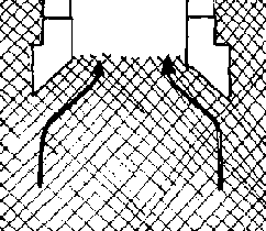
FIG. 9-4. CUTTING RING EFFECT
b. Construction Procedure
1) The general construction procedure to be fallowed when all
materials are assembled and ready for use is as follows.
· stack several
(usually 2 to 4) lining rings on top of a cutting ring which has been centered
and levelled in the bottom of the hole.
This initial column should be 2 to 3 meters high whether it is
composed of 1/2 met:er high rings or 1 meter high rings. If holes have beer made
in the rings to allow water entry. make sure that the holes slant up toward the
middle of the hole. Firmly attach rings together by whatever means you have
chosen.
Unstable ground can make the initial leveling/ plumbing of rings
very difficult. Where you can anticipate this, place a layer of gravel on the
bottom before lowering the cutting ring into the hole.
· after the lining
rings have been stacked on the cutting ring in the hole, well diggers will fill
in the space between the lining and the middle section lining with gravel. (See
Fig. 9-5.) Instead, some have placed several boards vertically in the" space to
act as a guide to help the column sink straight. (See Fig. 9-6.) Gravel is
easier and better to use because it will tend to fill in around the rings as
they are sunk, filling up any voids that might be created by over-pumping.
Gravel is also a convenient filler that is normally used to fill that space once
the bottom section is sunk.
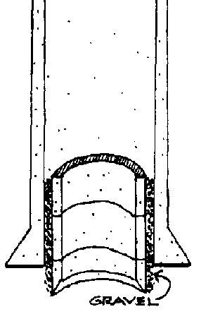
FIG. 9-5. GRAVEL USED TO GUIDE
SINKING RINGS
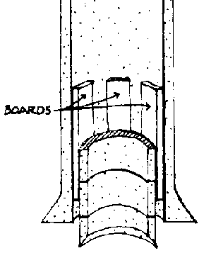
FIG. 9-6. BOARDS USED TO GUIDE
SINKING RINGS
· Remove soil and
water from inside the cutting ring thus causing the column to sink. Begin
digging in the middle and gradually work out to the edges of the column being
careful to remove soil evenly so as not to encourage the column to sink out of
alignment with the rest of the hole. (See Fig. 9-7.)
· Add more rings as
necessary as the column sinks. It is always necessary to have some overlap of
the sinking column and the middle section, and helpful to have up to 2 meters of
overlap to provide extra weight which will aid sinking and help to guide the
column down.
· Plan to add more
rings when it won't interrupt the sinking process. If it requires many people to
lower the rings, lower as many as you need in one or two sessions to avoid the
need to regather and reinstruct a large group of people.
· Continue digging
and sinking until water can no longer be removed from the hole fast enough to
allow further sinking. This will occur when well workers are digging in as much
as 1 meter of water. Remember,the farther this column is sunk into the water
bearing layer without going beyond it, the more water will be available from
that well. In commonly-found loose sand aquifers, the column of rings is usually
sunk between 2 and 4 meters beneath the bottom of the middle section lining. In
more consolidated aquifers, where water generally enters the well more slowly, a
greater depth can and should be reached.
· When sinking is
stopped it is necessary to have some overlap between the respective linings of
the middle and bottom sections. If the well has been completed in other than the
end of the dry season, it may be useful to leave several extra ring sections
stacked up into the middle section lining. If necessary, the well can then be
easily deepened at the end of the dry season when the water table is at its
lowest level. This will help to provide a permanent supply of
water.
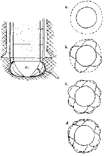
FIG. 9-7.
Digging steps while sinking lining
a. Dig a cone-shaped hole down to a convenient depth.
b. At four evenly spaced points in this cone-shaped hole, widen
the hole so that it reaches the width of the cutting ring.
c. Widen the hole at four more places between the areas already
widened.
d. Continue enlarging and widening the hole until the column of
rings sinks.
2. Dig-to-Bottom-and-Line
It is likely that this method will only be considered when:
· The middle section
of the well has been dug but not lined because there is little danger of soil
collapse. (A temporary lining could be used to reinforce the section or help
prevent caving.)
· The water beating
soil is firm enough to permit digging and removing water without great danger of
collapse.
Under these conditions an open hole can be dug down into the
aquifer. Even so, digging beneath the water table must be done very carefully
and can only reach a limited depth because of the increased danger of cave-ins
and collapse as the hole reaches deeper and deeper into the aquifer. The hole
should be dug as deep as is safely possible.
In the traditional well, the lining is begun by stacking rounded
stones to a 'neighs of between .5 and 1m. (See Fig.98.) A rock or brick masonry
wall is then built on top of the loose rock wall. Alternately, pre-cast rings
can be lowered in place or the lining could possibly be poured in place. If,
however, one has the equipment and supplies to cast concrete walls, it is
usually possible to sink the lining into place. This is much safer and can reach
a greater depth where there is any danger of cave-ins. Whatever lining method is
used is then continued up to the ground surface and the top section of the well
constructed.
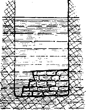
FIG. 9-8. TRADITIONAL WELL BOTTOM
3. Dig-and-Line-Short Sections
This particular method of digging into the water table is a
variation of the "dig-a-meter, pour-a-meter" method sometimes used to line the
middle section. The bottom section is dug and lined, usually 1/2 meter at a
time. As the aquifer is penetrated increasing amounts of water will enter the
well as the depth increases. Eventually a depth will be reached where the water
is coming into the well so fast that 1) it will wash away the mortar or concrete
before it has a chance to set, or 2) it will wash the walls in before there is
time to set a form, re-rod, and pour. From this point, use the following
procedure to extend the well as far into the aquifer as possible.
· Make sure that the
vertical re-rods extend beneath the bottom of the last pour so that the
subsequent sections can be attached to the existing lining.
· Dig in the center
of the hole to form an inverted cone which is about 40 cm deep and sloped out to
the bottom of the previous plastered section. (See Fig. 9-9a.) This tapered hole
keeps sand from washing out from behind the sections already lined.
· Quickly dig a
short section on one side down to about 30 cm. (See Fig. 9-9b.)
· Roughly plumb and
smooth the newly dug short section.
· Throw handfuls of
dry quick-setting cement mix onto the moist slowly collapsing sand.
· Moisten small
quantities of the mix and quickly plaster the short section. The mortar should
set (in about 5 minutes) before the water flow causes it to collapse. (See Fig.
9-9c.)
· Continue digging
and plastering short sections 30 cm deep around the hole until one complete 30
cm deep section is plastered. (See Fig. 9-9d.)
· Place re-rod;
leave extensions below plaster limit for connection to next pour.
NOTE: A quick-setting mortar mix consists of 1 part quicksetting
cement, 2 parts ordinary cement, and 1 part sand.
· Plaster over
re-rod with same quick-setting mix.
· Continue digging
and plastering short sections until 1) the water flowing into the well prevents
further plastering, or 2) you have reached the desired depth into the water
table. Do not leave any re-rod exposed to water. If necessary bend it up and
plaster, or cut it off and plaster.

FIG. 9-9. DIG AND LINE BOTTOM SECTION
NOTE: Special bricks may be made for covering places where water
is coming through the sand too quickly to permit plastering. These bricks are
made outside the well by spreading a 1 1/2 cm. layer of mortar on a flat
surface, and then cutting it into 15 cm.x 15 cm. squares with the edge of trowel
before the mortar dries. Whenever a spot is found where the water flow is so
rapid that it erodes even the rapid setting mix, one of these square mortar
bricks can be used as a stopper. Throw dry cement mix freely on the place where
the water is entering and slap a flat brick over it. Hold the brick in place
until the cement sets. It can then be plastered over in the same manner as the
rest of the short section being lined.
E. Bottom Plug or Filter
Most hand dug wells need a filter over the bottom of the well
that will allow only water and no fine particles of soil to enter the well. It
is especially critical where the aquifer is very fine sand. Only where wells are
sunk into hard rock is this not a consideration.
There are two different materials that can be used separately or
together: a gravel filter or a porous concrete plug.
1. Gravel Filter
A layer of gravel across the bottom of the well can serve as the
filter.
A minimum depth of 20 cm is suggested. The filter can be made
more effective by using 2 or more different sizes of gravel in separate layers
with the smallest size gravel on the bottom and the largest size gravel on top.
2. Concrete Plug
a. This is a slab of porous concrete which fits closely to the
inside diameter of the bottom lining. The slab can be cast in sections on the
surface and later lowered and placed in the well. It is placed in the well on
top of a shallow (10 - 15 cm) layer of gravel.
The slab should be made porous either by making holes in a
regular concrete slab or using a concrete mixture with very little sand as
described in the Cement Appendix. It can easily be cast on the surface digging a
mold out of the ground.
b. Making a bottom plug with the ground as the form
· Choose a fairly
flat section of ground that can be dug and will hold its shape.
· Draw a circle with
a diameter a few centimeters less than the inside diameter of the bottom
section.
· Dig out the circle
to a depth of 6 cm and make the bottom surface fairly even and square with the
sides. (See Fig. 9-10.)
· Put a divider
across the center of the circle so that you will then pour two halves of the
slab which can be more easily lowered and placed. The divider should be at least
6 cm high and be made from some suitable form material. (Alternately where a
divider is not available or appropriate, two circles can be drawn but then only
half of each dug out to form the two halves of the slab.) (See Fig.
9-10.)
· Place re-rod in
each half of the form. Leave handles or lowering hooks. When using 10 mm re-rod
it can be placed 20 cm apart or with 8 mm re-rod leave 15 cm between
re-rods.
· Pour concrete -
either standard or porous mix. If using non-porous concrete, make holes through
the slab with a piece of re-rod when the concrete begins to set.
· Cure for about a
week.
· Place in well on
10 to 15 cm of gravel.
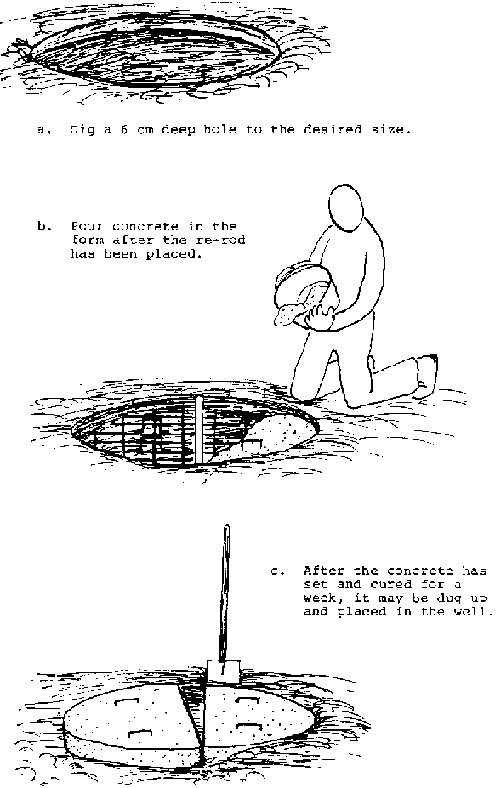
FIG. 9-10. CASTING THE BOTTOM
PLUG
