Back to Home
Page of CD3WD Project or Back to list of CD3WD Publications
 |  |  | Roadside Bio-Engineering - Site Handbook (DFID, 1999, 160 p.) |  |  | Section One - Stabilising slopes with civil and bio-engineering | |  | (introduction...) | | | 1.1 Problems of slopes and their solutions | | | 1.2 Steps for the stabilisation of slopes | | | (introduction...) | | | Step 1: Make an initial plan | | | Step 2: Prioritise the works | | | Step 3: Divide the site or slope into segments | | | Step 4: Assess the site | | | Step 5: Determine civil engineering works | | | Step 6: choose the right bio-engineering techniques | | | Step 7: Design the civil and bio engineering works | | | Step 8: Select the species to use | | | Step 9: Calculate the required quantities and rates | | | Step 10: Finalise priority against available budget | | | Step 11: Plan plant needs | | | Step 12: Arrange implementation and prepare documents | | | Step 13: Prepare for plant propagation | | | Step 14: Make the necessary site arrangements | | | Step 15: Prepare the site | | | Step 16: Implement the civil engineering works | | | Step 17: Implement the bio-engineering works | | | Step 18: Monitor the works | | | Step 19: Maintain the works |
|
Roadside Bio-Engineering - Site Handbook (DFID, 1999, 160 p.)
Section One - Stabilising slopes with civil and bio-engineering

Figure
This section provides:
· a brief
introduction to the common problems of slope instability, and ways of solving
them;
· a straightforward procedure to
identify and implement the appropriate treatments for each site, following a
series of logical steps summarised in Figure 1.3, on page
14.
1.1 Problems of slopes and their solutions
Ideally, the causes of slope instability would be well
understood and appropriate solutions would be easy to select. However, this is
rarely the case and engineers must make assumptions about the causes of slope
instability, based on their knowledge and experience of the terrain. This is
particularly true in Nepal, where slopes tend to be long and steep, and the
climatic variables are as yet poorly understood. Attaining a desired factor of
safety may not be feasible.
With such a variety of materials and sites, choosing
stabilisation techniques is a complicated process. There are many variables,
most of which cannot practicably be measured in the field. Therefore, it is not
possible to set quantitative limits on many of the parameters. This section
outlines instead a practical analysis to help the engineer to decide on the best
course of action.
Bio-engineering is not a substitute for civil engineering. It
offers engineers a set of tools to complement those already available in solving
a range of shallow slope problems.
Bio-engineering serves two distinct roles: providing additional
techniques for stabilising shallow failures and controlling erosion; and
enhancing civil engineering structures by protecting them and maximising their
effectiveness. In both roles, bio-engineering techniques must be carefully
integrated with civil engineering structures.
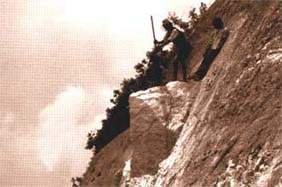
Every slope has a different variety of erosion and failure
processes at work on it; often, there will be more than one process affecting
each part of a slope. Freshly prepared slopes (i.e. those just cut or
filled) are usually subject to erosion, and so all slopes need to
be stabilised. These erosion and failure processes must be identified before
remedial work can be started. Examples of the most common problems are given in
Figure 1.11.
1 For a more comprehensive list of the
common forms of failure and erosion, refer to pages 12 and 13 of TRL Overseas
Road Note 16, Principles of low cost engineering in mountainous
regions.
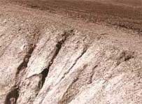
Shoulder erosion threatening the
edge of the road pavement. Even the smallest slope problems must be tackled
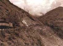
A deep planar slide on the Arniko
Highway has removed a portion of the road
Figure 1.1: Common types of erosion and slope failure
|
DESCRIPTION |
DEPTH |
MECHANISM* |
FUNCTION REQUIRED |
|
Rills and gullies form in weak, unprotected surfaces. Erosion
should also be expected on bare or freshly prepared slopes. |
Usually in the top 0.5 metre, but can become deeper if not
controlled. |
Erosion on the surface. |
Armour, Reinforce, Catch. |
|
Mass slope failure on a shallow slip plane parallel to the
surface. This is the most common type of landslide, slip or debris fall. The
plane of failure is usually visible but may not be straight, depending on site
conditions. It may occur on any scale. |
Frequently 0.5 metres or less below surface (or along a local
discontinuity). |
Planar sliding (translational landslide or debris slide).
|
Reinforce, Anchor, Catch, Drain. |
|
Mass slope failure on a deep, curved slip plane. Many small,
deep landslides are the result of this process. Large areas of subsidence may
also be due to these. |
Usually > 1.5 metres deep. |
Shear failure (rotational landslide). |
Anchor, Support, Drain. |
|
Slumping or flow where material is poorly drained or has low
cohesion between particles and liquefaction is reached. These sometimes look
similar to planar slides, but are due to flow rather than sliding. The resulting
debris normally has a rounded profile. |
Frequently 0.5 metres or less below surface. |
Slumping or flow of material when very wet. |
Drain, Reinforce. |
|
Collapse due to failure of the supporting material. This usually
takes the form of a rock fall where a weaker band of material has eroded to
undermine a harder band above. These are very common in mixed Churia strata.
|
0.5 to 2 metres in road cuts; deeper in natural cliffs. |
Debris fall or collapse. |
Reinforce, Support. |
* The mechanisms of failure or erosion are covered
in detail in the Reference Manual.
Figure 1.2: The main engineering functions of structures,
with examples of techniques
|
FUNCTION* |
CIVIL ENGINEERING TECHNIQUE |
BIO-ENGINEERING TECHNIQUE |
COMBINATION OF BOTH |
|
Catch |
Catch walls |
Contour grass lines or brush layers |
Catch wall with densely planted shrubs |
|
Catch fences |
Shrubs and large bamboo clumps |
Catch wall with bamboo clumps planted above |
|
Armour |
Revetments |
Mixed plant storeys giving complete cover |
Vegetated stone pitching |
|
Surface rendering |
Grass carpet |
jute netting with planted grass |
|
Reinforce |
Reinforced earth |
Densely rooting grasses, shrubs and trees |
Wire bolster cylinders and planted shrubs or trees |
|
Soil nailing |
Most vegetation structures |
Jute netting with planted grass |
|
Anchor |
Rock anchors |
Deeply rooting trees |
Combination of soil anchors and deeply |
|
Soil anchors |
|
rooting trees |
|
Support |
Retaining walls |
Large trees and large bamboo clumps |
Retaining wall with a line of large bamboo clumps |
|
Prop walls |
|
planted above |
|
Drain |
Masonry surface drains |
Downslope and diagonal vegetation lines |
Herringbone-pattern wire bolster cylinders and angled grass
lines |
|
Gabion and french drains |
Angled fascines or brush layers |
French drains and angled grass lines |
* The six main engineering functions are
defined in Section 1.2 below and are elaborated in the Reference
Manual.
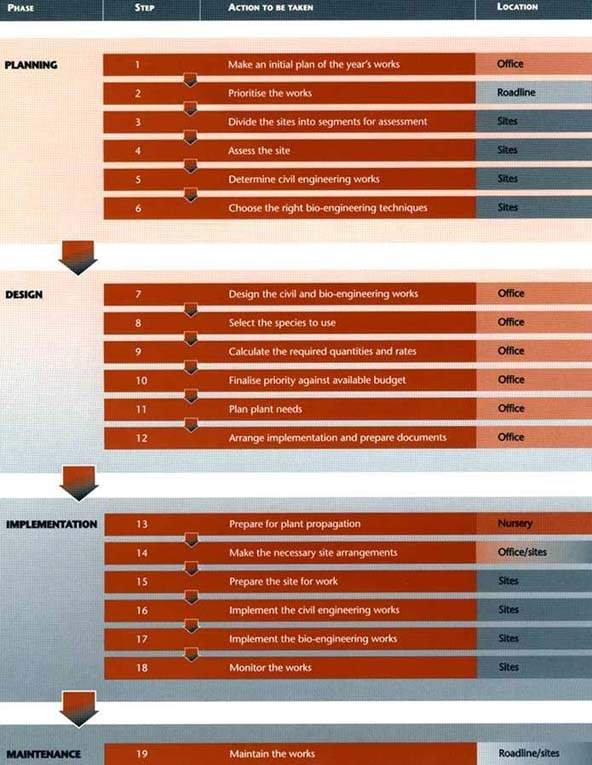
Figure 1.3: Flow chart to show the
progression of the steps for slope stabilisation
Figure 1.2 shows examples of civil and bio-engineering
techniques that have been devised to overcome these common
problems.
1.2 Steps for the stabilisation of slopes
In the steps outlined below and shown schematically by the flow
chart in Figure 1.3 on page 14, the engineer follows a logical procedure to plan
and implement the works.
These steps initially use as their basis the six main functions
of both civil engineering and bio-engineering techniques of slope stabilisation,
given in Figure 1.2. In more detail, engineering structures serve to:
Catch eroded material moving down the slope. Movement may
occur as a result of gravity alone, or with the aid of water as well. Material
is caught by a physical barrier such as a wall or the stems of vegetation;
Armour the slope against erosion from runoff and rain
splash. This is most effectively done using a continuous cover of low vegetation
(inert coverings such as stone pitching tend to be expensive over large areas).
Partial armouring is often provided, for example by using lines of grasses,
brush layers or wire bolsters;
Reinforce the soil by physically stiffening it to
increase its resistance to shear. Plant roots are effective at reinforcing soil;
Anchor surface material to deeper layers by soil pinning.
This helps to reduce mass movements at depths greater than provided by general
reinforcement. The roots of large plants emulate soil anchors or rock bolts;
Support a soil mass by buttressing. On a large scale, a
retaining wall or the roots of large plants (and their stems once they have
caught some debris) such as big bamboo clumps can buttress a soil mass. On a
micro scale individual large stones or smaller vegetation perform this function.
Drain excess water from the slope. Drier materials tend
to be more stable than wetter ones -many failures occur when the material
reaches a point of liquefaction. Standard civil engineering drains can be
provided; vegetation planted in lines angled down the slope help to drain the
surface layers.
Sites are assessed using a standard procedure. The choice of
stabilisation techniques (both standard civil and bio-engineering) depends on an
identification of the functions needed to stabilise and protect the slope. These
steps lead through the process to give a logical application of the techniques
available.
To implement slope stabilisation works including both civil and
bio-engineering, follow these steps.
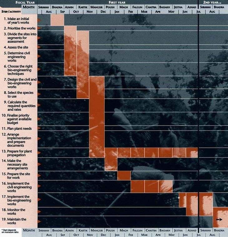
Figure 1.4: Summary calendar of
civil and bio-engineering
works
Step 1: Make an initial plan
Early in the fiscal year, you must prepare for the process of
checking all slopes along the road and planning the year's work. The calendar in
Figure 1.4 shows how the various steps involved, as described above, will be
scheduled through the year.
Note that there are three critical points on this calendar; all
are governed by seasons. These are:
· seed collection,
which starts in Mangsir for many species;
·
civil engineering works, which must be complete before the rains start in
Jestha; and
· site planting, which usually
starts in late Jestha or Ashad, as soon as the rains are reliable.
All of the other activities must be completed on schedule for
these to be carried out in the right season. This accounts for the heavy
planning and design load early in the fiscal
year.
Step 2: Prioritise the works
Inspect the road and make a list of the sites that require
treatment. Prioritise them according to the importance of stabilisation.
Weighing the seriousness of the existing or potential failure
against the damage it could cause helps to prioritise and schedule works. Figure
1.5 shows the priority to be given to different slope movement problems. The
scale goes from a distinct threat to human life (e.g. houses might be
lost or the entire road could be carried away) to the situation where a slope
problem can cause only limited damage (e.g. occasional blocking of
drains), and where treatment is more of a preventative measure (see Figure 1.5).
In many cases, budget constraints allow only the higher priority
sites to be addressed. Sites up to priority 3 should always be treated if at all
possible. However, the aim should be to move towards treatment of all sites
under a regular maintenance programme.
Figure 1.5: Prioritisation of repair work (from the
perspective of the Department of Roads)
|
EXPECTED CONSEQUENCE IF THE SITE IS NOT TREATED |
PRIORITY RATING |
|
Slope movement threatens houses |
Priority 1 (i.e. very high priority) |
|
Slope movement threatens complete loss of road |
Priority 2 |
|
Slope movement threatens partial loss of road |
Priority 3 |
|
Slope movement threatens complete road blockage |
Priority 3 |
|
Debris may fall on top of pedestrians or vehicles and cause
injury |
Priority 3 |
|
Slope movement threatens loss of productive farmland |
Priority 4 |
|
Slope movement threatens blockage of drains |
Priority 4 |
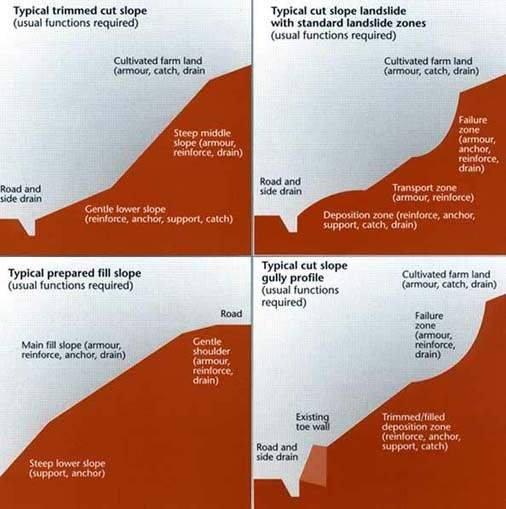
Figure 1.6: Typical slope
segments, showing patterns of material
movement
Step 3: Divide the site or slope into segments
A slope segment can be defined as a length of slope with a
uniform angle and homogeneous material that is likely to erode or fail in a
uniform manner.
The mechanical, hydrological and biological processes at work in
a slope are many and complex. Nevertheless, before any remedial work can begin,
it is necessary to identify the major factors contributing to instability in
order to decide on appropriate action. The assessment and treatment of each site
is based on the use of one or more techniques for each segment. So it is
necessary to divide the slope into its component segments. Some common examples
of slopes are given in Figure 1.6.
While carrying out this step on site, it is useful to sketch the
site on the pro forma given in Annex A.
Before proceeding to Step 4, you should have a good knowledge of
the site. You should know how many segments make up the slope, and have an idea
of how the main processes at work within each segment contribute to the overall
instability of the site.
From now on, each segment of slope must be considered a separate
entity for treatment: both civil engineering and bio-engineering techniques
should be planned for each segment rather than for an entire site.
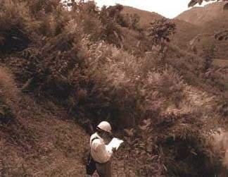
Careful site inspection Is
essential for successful stabilisation
Figure 1.7: Common types of erosion and slope failure
|
MECHANISM* |
DESCRIPTION |
DEPTH |
|
Erosion on the surface. |
Rills and gullies form in weak, unprotected surfaces.
Erosion should also be expected on bare or freshly prepared slopes. |
Usually in the top 0.1 metre, but can become deeper if not
controlled. |
|
Gully erosion |
Gullies that are established in the slope continue to develop
and grow bigger. Large gullies often have small landslides along the sides.
|
Usually in the top 0.5 metre, but can become deeper if not
controlled. |
|
Planar sliding (translational landslide or debris
slide). |
Mass slope failure on a shallow slip plane parallel to
the surface. This is the most common type of landslide, slip or debris fall. The
plane of failure is usually visible but may not be straight, depending on site
conditions. It may occur on any scale. |
Frequently 0.5 metre or less below surface (or along a local
discontinuity). |
|
Shear failure (rotational landslide). |
Mass slope failure on a deep, curved slip plane. Many small,
deep landslides are the result of this process. Large areas of subsidence may
also be due to these. |
Usually > 1.5 metres deep. |
|
Slumping or flow of material when very wet. |
Slumping or flow where material is poorly drained or has
low cohesion between particles and liquefaction is reached. These sometimes
appear afterwards like planar slides, but are due to flow rather than sliding.
The resulting debris normally has a rounded profile. |
Frequently 0.5 metre or less below surface. |
|
Debris fall or collapse. |
Collapse due to failure of the supporting material. This
normally takes the form of a rock fall where a weaker band of material has
eroded to undermine a harder band above. These are very common in mixed Churia
strata. |
0.5 to 2 metres in road cuts; deeper in natural cliffs. |
|
Debris flow |
In gullies and small, steep river channels (bed gradient usually
more than 15°), debris flows can occur following intensive rain storms.
This takes the form of a rapid but viscous flow of liquefied mud and debris.
|
The flow depth is usually 1 to 2 metres deep. |
* The mechanisms of failure or erosion are covered
in detail in the Reference
Manual.
Step 4: Assess the site
This is the most important step, and the one on which you must
spend the most time. You must make a site visit, and you will need:
· either some copies
of the pro forma in Annex A or a notebook;
· a 30-metre tape measure;
· a clinometer or an Abney level
(if you do not have one of these, take this handbook with you and use the angled
slope lines in Annex A to estimate slope angle in profile); and
· an altimeter, or maps or site
drawings of the roadline that show the altitude.
Carefully assessing a site, through an investigation on the
ground, is the key to applying good engineering practice. Without proper
investigation and assessment, both civil and bio-engineering techniques are
likely to fail. This section gives only a very brief guide; more details on site
assessment are provided in Section 2 of the Reference Manual.
The objective of Step 4 is to arrive at a more detailed
appreciation of the factors contributing to instability within each slope
segment. In order to achieve this, you will need to look carefully at each
segment of the site and note down the following facts (more details are given in
the paragraphs below).
|
Erosion and failure processes |
List |
|
Other factors |
List |
|
Slope angle(s) |
3 classes: <30º, 30-45º, or>45º
|
|
Slope length |
2 classes: 15 metres or>15 metres |
|
Material drainage |
2 classes: good or poor |
|
Site moisture |
4 classes: wet, moist, dry or very dry |
|
Altitude |
Determine: use an altimeter, map site drawing |
Figure 1.8: The main physical factors affecting slopes
|
POTENTIAL FACTOR |
DESCRIPTION |
|
Fault lines |
Small fault lines may cause differential erosion in parts of the
site. |
|
Springs |
There may be seasonal springs within the site, which cause
localised problems of drainage or slumping. |
|
Slip planes |
The main plane of failure may not be the only one. Many sites
have secondary, smaller slip planes additional to the main failure mechanism
|
|
Large gullies |
Large gullies nearby may erode backwards and damage the site.
Alternatively, they may discharge, causing deposition on the site. |
|
Landslides |
Nearby landslides may extend headwards or sideways, or may
supply debris on to the site. |
|
River flooding |
A large river below the site may flood badly, damaging the site
by either erosion or deposition, or a combination of both. |
|
River cutting |
Rivers below the site may move in floods, undercutting the toe
of the site. |
|
Catchments |
If there is an extended catchment area above the site, it could
lead to a large discharge, which causes bad damage by erosion or deposition.
|
|
Drain discharge |
The discharge of drainage water must be safeguarded to avoid
causing erosion or mass failures. Poorly sited or inadequately protected
discharge points can cause severe problems. |
|
Khet and kulo |
Khet (rice paddy) land or a kulo (irrigation channel) above a
site usually means a large volume of water infiltrating into the slope, with a
greater potential for failure or large-scale erosion. |
|
Construction activities |
Construction activities on or near the site may lead to
undermining through excavations, or surcharging through spoil disposal in the
wrong places. |
Erosion and failure processes
Each site has a different variety of erosion processes at work,
which must be identified before remedial work can be started; often, there will
be more than one process affecting each slope segment. A list of the erosion and
failure problems is given in Figure 1.7. But remember that most sites, however
small, are the result of a combination of these processes. It is assumed that
freshly prepared slopes (i.e. those just cut or filled) are subject to
erosion, and so all slopes need to be treated1.
1 For a more comprehensive list of the
common forms of failure and erosion, refer to pages 12 and 13 of TRL Overseas
Road Note 16, Principles of low cost engineering in mountainous
regions.
List the erosion and failure processes at work in each segment
of slope and mentally crosscheck it against the functions required of the
stabilisation measures. Sketch these on paper for your later reference and to
help with the design of structures. If you need more details on any aspect of
site assessment, refer to Section 2 of the Reference Manual.
Other factors
You must identify and note down all of the physical factors
affecting a site. Those additional to the basic features of slope segments are
listed in Figure 1.8. Some are internal (e.g. springs) while others are
external (e.g. river undercutting).
Slope angle(s)
Record the slope angles and assign each segment to one of three
classes: <30°, 30 - 45°, or > 45° Slopes of less than
30° will need only mild treatment;) those falling in the other two classes
will require more substantial stabilisation.
Figure 1.9: Common characteristics of well-drained and poorly
drained soils
|
MATERIAL DRAINAGE
CHARACTERISTICS |
TENDENCY TOWARDS GOOD DRAINAGE |
TENDENCY TOWARDS POOR DRAINAGE |
|
Overall drainage |
Freely draining material; dries quickly after rain storms |
Slowly draining material; tends to remain wet for long periods
after rain; behaves like firm dahi (curd) |
|
Soil particle size |
Coarse textures; loams and sandy soils |
Fine textures; clays and silts |
|
Porosity |
Large inter-connecting pores |
Small pores |
|
Material types |
Stony colluvial debris; fragmented rock; sandy and gravelly
river deposits |
Residual soils of fine texture; debris from mud flows, slumps,
etc; rato mato (red clay loam soil) |
|
Slope types |
Fill slopes; cut slopes in stony debris (colluvium) |
Cut slopes in original consolidated ground |
Slope length
Record the length of each segment of the site as < 15 metres
or > 15 metres. A slope length of 15 metres represents a practical dividing
line between 'big' and 'small' site segments. Slope segments longer than 15
metres are prone to greater risks, for example of gullying. Also, cost
constraints may lead to a compromise over the desired intensity of work.
Segments with very long slopes (greater than 30 metres) are singled out for
special consideration in step 5 (see Figure 1.11).
Material drainage
This relates to the internal porosity of soils and the
likelihood of their reaching saturation, losing cohesion and starting to flow.
Materials with poor internal drainage tend to have more clay than sand. They are
prone to slumping at a shallow depth (e.g. < 500 mm) if they
accumulate too much moisture. In such a case, stabilisation requires some kind
of drainage in addition to other functions.
For convenience, materials need to be classed only into 'good'
or 'poor' drainage. Figure 1.9 provides a guide.
Segment moisture
The moisture regime of the entire site must be considered
although, in the field, this can only be estimated. In assessing sites, it is
necessary to determine into which of four categories each segment falls.
|
Wet: |
permanently damp sites (e.g. north-facing gully sites).
|
|
Moist: |
sites that are reasonably well shaded or moist for some other
reason. |
|
Dry: |
generally dry sites. |
|
Very dry: |
sites that are very dry; these are usually quite hot as well
(e.g. south-facing cut slopes at low altitudes). |
Figure 1.10 summarises the main factors and how they can be
identified.
Altitude
Altitude is the main determinant of temperature in Nepal and
therefore regulates the local climate to a large extent. It is necessary to know
the altitude to a reasonable degree of accuracy (ideally +100 metres) when the
actual species are selected for bio-engineering works.
Figure 1.10: Environmental factors indicating site moisture
characteristics
|
SITE MOISTURE FACTOR |
TENDENCY TOWARDS DAMP SITES |
TENDENCY TOWARDS DRY SITES |
|
Aspect |
Facing N, NW, NE and E |
Facing S, SW, SE and W |
|
Altitude |
Above 1 500 metres; particularly above 1 800 metres |
Below 1 500 metres; deep river valleys surrounded by ridges
|
|
Topographical location |
Gullies; lower slopes; moisture accumulation and seepage areas
|
Upper slopes; spurs and ridges; steep rocky slopes |
|
Regional rain effects |
Eastern Nepal in general; the southern flanks of the Annapurna
Himal |
Most of Mid Western and Far Western Nepal |
|
Rain shadow effect |
Sides of major ridges exposed to the monsoon rain-bearing wind
|
Deep inner valleys; slopes sheltered from the monsoon by higher
ridges to the south |
|
Stoniness and soil moisture holding capacity |
Few stones; deep loamy* and silty soils |
Materials with a high percentage volume of stones; sandy soils
and gravels |
|
Winds |
Sites not exposed to winds |
Large river valleys and the Terai |
|
Dominant vegetation |
e.g. amliso, nigalo, bans, chilaune, katus, lali gurans,
utis |
e.g. babiyo, khar, dhanyero, imili, kettuke, khayer,
salla |
* Loam is the name given to a soil with moderate
amounts of sand, silt and clay, and which is therefore intermediate in texture
and best for plant growth.
Figure 1.11: Assessing the requirements for civil engineering
treatments
|
QUESTION |
FUNCTIONAL IMPLICATION |
ACTION IF THE
ANSWER IS "YES" |
USE OF BIO-
ENGINEERING |
|
Is the slope segment or the whole site subject to a deep-seated
(>1 metre depth) shear (rotational) failure? |
Major reinforcing, anchoring or physical support required. |
If the failure plane can be identified, use conventional civil
retaining walls to support the toe.
Alternatively, it may be possible to remove weight from higher
up on the slope by heavy trimming. |
Bio-engineering measures will mainly be used to armour backfill
and foundation areas.
If trimming is carried out, bio-engineering measures will be
needed to armour the new bare surfaces. |
|
Is the slope segment very long (greater than about 30 metres),
steep and in danger of a mass failure below the surface? |
Reinforcing or physical support is required.
Armouring is also required. Bio-engineering measures alone may
be adequate, but where a large volume of surface runoff is possible, physical
structures are also necessary. |
If suitable foundations are available, use retaining walls to
break the slope into smaller, more stable lengths.
Some other kind of physical scour check should be used, such as
wire bolster cylinders. |
Bio-engineering measures must be designed to reinforce and
armour the slope between the physical structures. |
|
Is the foot of the slope undermined, threatening higher segments
or the whole Slope above? |
Strong physical support is required. Bio-engineering measures
will enhance civil structures. |
Investigate the necessity of building revetment, toe or prop
walls. |
Bio-engineering measures will mainly be used to armour backfill
and foundation areas. |
|
Is there a distinct overhang or are there large boulders poorly
supported by a soft, eroding band? |
Localised physical support or anchoring are required. Support
can be given using a civil structure. |
Consider prop walls or dentition to support the overhang.
|
The direct seeding of shrubs on fragmented rocky slopes can
provide anchorage. |
|
Does the slope segment have a rough surface; or is it covered in
loose debris; or is it a fractured rocky slope; or does it have any very steep
or overhanging sections, however small? |
Armouring is required, but only after the slope has been altered
to stop it shedding loose material. |
Trim the slope as far as possible to attain a smooth, clean
surface with a straight profile in cross-section. |
The trimmed slope will need to be armoured afterwards by the
appropriate bio-engineering measure. |
|
Is there water seepage, a spring or groundwater on the site, or
a danger of mass slumping after heavy rain? |
Deep drainage is required. |
Investigate the need for a drainage system involving french or
other sub-surface drains, depending on site conditions. |
Deep drains can be enhanced by surface bio-engineering systems
(e.g. downslope planted grass lines). |
|
Is the slope made up of poorly drained material, with a high
clay content? |
Techniques used on this sort of material must be designed to
drain rather than accumulate moisture. |
There is a danger of shallow slumping. Investigate the need for
a surface drainage system. |
An appropriate bio-engineering system (e.g. downslope
planted grass lines) is often adequate on its own. |
|
Is the site a major gully, subject to occasional erosive
torrents of water? |
Major drainage is already present; heavy armouring is required.
|
Use masonry check dams to reduce the scouring effect.
|
Between the check dams, use large bamboo planting, live check
dams or vegetated stone pitching. |
Step 5: Determine civil engineering works
At this stage, standard civil engineering structures (e.g.
gabion and other types of retaining structures, breast walls, prop walls and
revetments; check dams; masonry drainage systems) should be considered. In later
stages, small-scale civil engineering structures used only for surface
protection (i.e. stone pitching and jute netting) are considered as
options where appropriate.
Some sites will not require the building of structures, but will
instead be stabilised using only bio-engineering techniques. In most cases,
however, bio-engineering techniques will also be employed to enhance the
effectiveness of civil engineering structures. The series of questions in Figure
1.11 helps to simplify the process of assessing the requirements for major civil
engineering treatments. These must be integrated with bio-engineering measures,
but normally need to be implemented first.
If civil engineering structures are to be used, they must be
designed and constructed according to normal practice. Apart from the key design
details referred to in Section 2, these are beyond the scope of this manual. A
useful reference work is TRL Overseas Road Note 16, Principles of low cost
road engineering in mountainous terrain.
The next step concentrates on shallow (< 500 mm depth)
stabilisation and surface protection using bio-engineering techniques, and on
areas around civil engineering structures.
|
How to use the flow chart in Figure 1:12
There are two methods: either
1. Use it as a prescriptive system to determine
the treatments required, based on the site assessment described in step 4;
or
2. If you have already determined a treatment, use
it to check that your choice is suitable against normal practice. |
Step 6: choose the right bio-engineering techniques
Having completed step 5, any deeper-seated problems will have
been addressed by conventional civil engineering measures, such as retaining
walls and drainage systems. This step gives details of bio-engineering and other
related techniques for protecting the surface, stabilising the upper 500 mm, and
improving surface drainage; and for enhancing and protecting large civil
engineering structures. These are required as part of the whole stabilisation
package; bio-engineering must be fully integrated with any civil engineering
structures.
The flowchart in Figure 1.12 suggests appropriate techniques for
different slope segments. It is assumed that these are combined with appropriate
civil engineering structures where necessary to enhance slope stability. Many
factors determine the optimum technique or combination of techniques, but only
the most important have been included here.
The seven columns in Figure 1.12, (a) to (g), are summarised
below.
(a) Slope angle(s)
3 classes: <30º, 30 -
45°, or >45° (measured in step 4).
(b) Slope length
2 classes: <15 metres or >15
metres (measured in step 4).
(c) Material drainage
2 classes: good or poor
(estimated in step 4).
(d) Site moisture
2 classes: wet/moist or dry/very dry
(combined from the four estimated in step 4)1.
1 The four classes determined in step 4
(as well as the altitude of the site) are required to establish the actual
species to be used for bio-engineering, in step 8.
(e) Potential problems
The potential problems to be
encountered on each slope segment have been identified in step 4.
(f) Function required
Once you have assessed the most
likely potential problems on a slope segment you can select the most appropriate
engineering functions required (i.e. catch, armour, reinforce, anchor,
support or drain) for each segment. In bio-engineering, the functions required
by the treatment determine the plant types used and the way they are propagated.
This is given in detail in step 8.
Figure 1.12: Choosing a bio-engineering technique
|
START (a)
SLOPE
ANGLE |
®(b)
SLOPE
LENGTH |
®
(c)
MATERIAL
DRAINAGE |
®
(d)
SITE
MOISTURE |
®
(e)
PREVIOUS/POTENTIAL
PROBLEMS ‡ |
®(f)
FUNCTIONS
REQUIRED |
®
(g)
TECHNIQUE(S) |
|
> 45° |
> 15
metres |
Good |
Damp |
Erosion slumping |
Armour, reinforce drain |
Diagonal grass lines |
|
|
|
Dry |
Erosion |
Armour, reinforce |
Contour grass lines |
|
|
Poor |
Damp |
Slumping, erosion |
Drain, armour, reinforce |
1 Downslope grass lines and vegetated stone pitched rills
or
2 Chevron grass lines and vegetated stone pitched rills |
|
|
|
Dry |
Erosion, slumping |
Armour, reinforce dram |
Diagonal grass lines |
|
<15
metres |
Good |
Any |
Erosion |
Armour, reinforce |
1 Diagonal grass lines or
2 Jute netting and randomly
planted grass |
|
|
Poor |
Damp |
Slumping, erosion |
Drain, armour, reinforce |
1 Downslope grass lines or
2 Diagonal grass lines
|
|
|
|
Dry |
Erosion, slumping |
Armour reinforce drain |
1 Jute netting and randomly planted grass or
2 Contour
grass tines or
3 Diagonal grass lines |
|
30° - 45° |
>15
metres |
Good |
Any |
Erosion |
Armour, reinforce, catch |
1 Horizontal bolster cylinders and shrub/tree planting or
2 Downslope grass lines and vegetated stone pitched rills or
3 Site grass
seeding, mulch and wide mesh jute netting |
|
|
Poor |
Any |
Slumping, erosion |
Dram, armour, reinforce |
1 Herringbone bolster cylinders & shrub/tree planting
or
2 Another drainage system and shrub/tree planting |
|
<15
metres |
Good |
Any |
Erosion |
Armour, reinforce, catch |
1 Brush layers of woody cuttings or
2 Contour grass
lines or
3 Contour fascines or
4 Palisades of woody cuttings or
5 Site
grass seeding, mulch and wide mesh jute netting |
|
|
Poor |
Any |
Slumping, erosion |
Dram, armour, reinforce |
1 Diagonal grass lines or
2 Diagonal brush layers
or
3 Herringbone fascines and shrub/tree planting or
4 Herringbone bolster
cylinders & shrub/tree planting or
5 Another drainage system and
shrub/tree planting |
|
< 30° |
Any |
Good |
Any |
Erosion |
Armour, catch |
1 Site seeding of grass and shrub/tree planting or
2
Shrub/tree planting |
|
|
Poor |
Any |
Slumping, erosion |
Drain, armour, catch |
1 Diagonal lines of grass and shrubs/trees or
2
Shrub/tree planting |
|
<15
metres |
Any |
Erosion |
Armour catch |
Turfing and shrub/tree planting |
|
Base of any slope |
Planar sliding or
shear failure |
Support, anchor, catch |
1 Large bamboo planting or
2 Large tree planting |
Special conditions
|
Any * |
Any* |
Any* |
Any* |
Planar sliding,
ear failure |
Reinforce, anchor |
Site seeding of shrubs/small trees † |
|
> 30° |
Any |
Any rocky material |
Debris fall |
Reinforce, anchor |
Site seeding of shrubs/small trees |
|
Any loose sand |
Good |
Any |
Erosion |
Armour |
Jute netting and randomly planted grass |
|
Any rato mato |
Poor |
Any |
Erosion, slumping |
Armour, drain |
Diagonal lines of grass and shrubs/trees |
|
Gullies
< 45° |
Any gully |
Erosion (major) |
Armour, reinforce, catch |
1 Large bamboo planting or
2 Live check dams or
3
Vegetated stone pitching |
* Possible overlap with parameters described in the
rows above. † May be required in combination with other techniques listed
on the rows above. ‡ Only the common potential problems listed in Figure
1.7 are given here. 'Any rocky material' is defined as material into which
rooted plants cannot be planted, but seeds can be inserted in holes made with a
steel bar. 'Any loose sand' is defined as any slope in a weak, unconsolidated
sandy material. Such materials are normally river deposits of recent geological
origin. 'Any rato mato' is defined as a red soil with a high clay content. It is
normally of clay loam texture, and formed from prolonged weathering. It can be
considered semi-lateritic. Techniques in bold type are preferred. Chevron
pattern: <<<<< (like a sergeant's stripes). Herringbone pattern:
¬¬¬¬¬ (like the bones of a fish).
(g) Techniques
One or more techniques that are known
to be successful on sites for each category are given. However, the general
picture may not cover every case and so this flowchart cannot be considered to
be fully comprehensive: some local variation may be needed and this, of
course, is the reason for having an engineer on site.
Once this step has been completed, it is possible to move on to
the detailed design of the works for each
site.
Step 7: Design the civil and bio engineering works
Design the civil and bio-engineering works using normal
procedures. It is more cost effective to design the works so that they are
carried out in a fully integrated way. As usual, you should bear in mind the
resources and budget available for the work. Make the designs as detailed as you
can at this stage.
Practical design considerations for the most common civil
engineering structures are given in Section 2.
Details of the design of bio-engineering works are given in
Section 3.
Padang bans is a valuable small
bamboo for bio-engineering works on high-altitude
roads
Step 8: Select the species to use
It is important to select the right species for use in each
bio-engineering technique. To do this there are three factors to consider:
function/technique, propagation and site suitability.
Function/technique
Having worked through the previous steps, you will have
determined the functions required for each slope segment and will now have
identified the techniques you need to use. The most appropriate class of plant
to use depends on the techniques. These are summarised in Figure 1.13, but are
also shown in the table listing the main bio-engineering species (Figure 1.14).
Propagation
There are various methods of propagation appropriate for the
main plant classes, but individual species can be propagated only by certain of
these methods. The method of propagation to be used is often determined by the
function required and the bio-engineering technique being used. For example, if
grass lines are to be planted, the species chosen must be capable of propagation
from slip cuttings; if brush layering, palisades or fascines are to be used, the
shrubs or small trees must be capable of growing from hardwood cuttings.
Site suitability
Whatever the function and propagation method required of the
plants by the bio-engineering technique, the plants selected must be able to
grow in the site being treated. The suitability of each species to their growing
sites is complex, but there are some straightforward rules that simplify the
matter. The three main aspects of the environment affecting plant growth are as
follows.
· Temperature. This
is very closely related to altitude for most of Nepal. In choosing the species,
therefore, the site altitude measured in step 4 is used.
· Moisture. This is very
difficult to quantify. It was assessed in step 4 for the site and classed as one
of wet, moist, dry or very dry. This is now used to choose the species.
· Nutrients. The main species
used in bio-engineering are all tolerant of very poor soils. Therefore the
nutrition factor can be ignored at this stage.
The final choice of species according the technique for which it
is to be used, and the site characteristics of altitude and moisture, is made by
reference to Figure 1.14.
Figure 1.13: Bio-engineering techniques and appropriate plant
classes
|
TECHNIQUES |
PLANT CLASS TO USE |
PACE REFERENCE
TO FIGURE 1.14 |
|
Planted grass lines (all configurations) and vegetated stone
pitching gully beds |
Grasses grown from slip/rhizome cuttings |
page |
28 |
|
Brush layers, palisades, live check dams, fascines and vegetated
stone pitching walls |
Shrubs */ small trees grown from hardwood cuttings |
page |
30 |
|
Large bamboo planting |
Large bamboos |
page |
33 |
|
Site seeding with grass |
Grasses grown from seed |
page |
29 |
|
Turfing |
Small sward grasses |
page |
29 |
|
Site seeding with shrubs/small trees |
Robust shrubs/small trees grown from seeds |
page |
32 |
|
Shrub/small tree planting |
Shrubs/small trees (grown from seeds/polypots) |
page |
31 |
|
Large tree planting |
Large trees (grown from seeds/polypots) |
page |
31 |
* A shrub is a woody plant with multiple stems
growing up from the ground; a tree has usually one stem growing up from the
ground. For bio-engineering purposes, shrubs and small stature trees have the
same functions, since the rooting patterns tend to be similar.
Figure 1.14: Selection of species for bio-engineering by
groups of techniques
Planted grass lines (all configurations) and vegetated stone
pitching gully beds
These grasses are grown from slip or rhizome cuttings
|
MOISTURE |
WET |
MOIST |
DRY |
VERY DRY |
|
ALTITUDE |
|
Grasses |
|
|
2500 - 2000 m |
Padang bans |
Padang bans |
Tite nigalo bans |
|
|
Tite nigalo bans |
Phurke |
|
|
|
|
Tite nigalo bans |
|
|
|
2000 - 1500 m |
Amliso |
Amliso |
Amliso |
Babiyo |
|
Kans |
Babiyo |
Babiyo |
Kans |
|
Katara khar |
Kans |
Kans |
Khar |
|
Padang bans |
Katara khar |
Katara khar |
|
|
Phurke |
Khar |
Khar |
|
|
Tite nigalo bans |
Padang bans |
Phurke |
|
|
|
Phurke |
Tite nigalo bans |
|
|
|
Tite nigalo bans |
|
|
|
1500 - 1000 m |
Amliso |
Amliso |
Amliso |
Babiyo |
|
Kans |
Babiyo |
Babiyo |
Dhonde |
|
Katara khar |
Dhonde |
Dhonde |
Kans |
|
Khus |
Kans |
Kans |
Khar |
|
Phurke |
Katara khar |
Katara khar |
Narkat |
|
Sito |
Khar |
Khar |
|
|
Tite nigalo bans |
Khus |
Khus |
|
|
|
Narkat |
Narkat |
|
|
|
Phurke |
Phurke |
|
|
|
Sito |
Sito |
|
|
|
Tite nigalo bans |
|
|
|
1000 - 500 m |
Amliso |
Amliso |
Amliso |
Babiyo |
|
Kans |
Babiyo |
Babiyo |
Dhonde |
|
Katara khar |
Dhonde |
Dhonde |
Kans |
|
Khus |
Kans |
Kans |
Khar |
|
Phurke |
Katara khar |
Katara khar |
Narkat |
|
Sito |
Khar |
Khar |
|
|
|
Khus |
Khus |
|
|
|
Narkat |
Narkat |
|
|
|
Phurke |
Phurke |
|
|
|
Sito |
Sito |
|
|
500 m - Terai |
Amliso |
Amliso |
Amliso |
Babiyo |
|
Kans |
Babiyo |
Babiyo |
Dhonde |
|
Katara khar |
Dhonde |
Dhonde |
Kans |
|
Khus |
Kans |
Kans |
Khar |
|
Sito |
Katara khar |
Katara khar |
Narkat |
|
|
Khar |
Khar |
|
|
|
Khus |
Khus |
|
|
|
Narkat |
Narkat |
|
|
|
Sito |
Sito |
|
This table gives the main species used for
bio-engineering in Nepal. A range of plants is available for each particular
location. A list of all tested bio-engineering species is given in Annex B. Full
details of the main bio-engineering species are given in the Reference
Manual.
Figure 1.14: Selection of species for bio-engineering by
groups of techniques
Species for grass seeding and turfing
|
Moisture |
Wet |
Moist |
Dry |
Very dry |
|
Altitude |
Clump grasses (for seeding) |
Small sward grass (for turfing) |
Clump grasses (for seeding) |
Small sward grass (for turfing) |
Clump grasses (for seeding) |
Small sward grass (for turfing) |
Clump grasses (for seeding) |
Small sward grass (for turfing) |
|
2500 -
2000 m |
|
|
|
|
|
|
|
|
|
2000 - |
Kans |
Dubo |
Babiyo |
Dubo |
Babiyo |
Dubo |
Babiyo |
|
|
1500 m |
Katara khar |
|
Kans |
|
Kans |
|
Kans |
|
|
Phurke |
|
Katara khar |
|
Katara khar |
|
Khar |
|
|
|
|
Khar |
|
Khar |
|
|
|
|
|
|
Phurke |
|
Phurke |
|
|
|
|
1500- |
Kans |
Dubo |
Babiyo |
Dubo |
Babiyo |
Dubo |
Babiyo |
|
|
1000m |
Katara khar |
|
Dhonde |
|
Dhonde |
|
Dhonde |
|
|
Phurke |
|
Kans |
|
Kans |
|
Kans |
|
|
Sito |
|
Katara khar |
|
Katara khar |
|
Khar |
|
|
|
|
Khar |
|
Khar |
|
|
|
|
|
|
Phurke |
|
Phurke |
|
|
|
|
|
|
Sito |
|
Sito |
|
|
|
|
1000 - |
Kans |
Dubo |
Babiyo |
Dubo |
Babiyo |
Dubo |
Babiyo |
|
|
500 m |
Katara khar |
|
Dhonde |
|
Dhonde |
|
Dhonde |
|
|
Phurke |
|
Kans |
|
Kans |
|
Kans |
|
|
Sito |
|
Katara khar |
|
Katara khar |
|
Khar |
|
|
|
|
Khar |
|
Khar |
|
|
|
|
|
|
Phurke |
|
Phurke |
|
|
|
|
|
|
Sito |
|
Sito |
|
|
|
|
500m- |
Kans |
Dubo |
Babiyo |
Dubo |
Babiyo |
Dubo |
Babiyo |
|
|
Terai |
Katara khar |
|
Dhonde |
|
Dhonde |
|
Dhonde |
|
|
Sito |
|
Kans |
|
Kans |
|
Kans |
|
|
|
|
Katara khar |
|
Katara khar |
|
Khar |
|
|
|
|
Khar |
|
Khar |
|
|
|
|
|
|
|
Sito |
|
Sito |
|
|
|
This table gives the main species used for
bio-engineering in Nepal. A range of plants is available for each particular
location. A list of all tested bio-engineering species is given in Annex B. Full
details of the main bio-engineering species are given in the Reference
Manual.
Step 9: Calculate the required quantities and rates
Calculate the quantities and rates required for the works. This
is a standard procedure and, for work by the Department of Roads, must follow
the schedules established by the government for this purpose.
Rate analysis norms for bio-engineering are given in the
Reference
Manual.
Step 10: Finalise priority against available budget
You can now finalise the work to be undertaken in the year's
programme. This entails determining the right balance between the resources
available and the seriousness of the failures on the sites that need to be
stabilised.
The prioritisation made in step 2 showed how important it is to
stabilise each site. This should be re-examined to check that the higher
priority sites can all be covered. In certain cases it may be necessary to
return to steps 7 and 8, to reconsider the design of the civil and
bio-engineering works with a view to reducing costs and covering more sites.
Figure 1.14: Selection of species for bio-engineering by
groups of techniques
Species for brush layers, palisades, live check dams,
fascines and vegetated stone pitching walls
Shrubs/small trees grown from
hardwood cuttings
|
Moisture |
Wet |
Moist |
Dry |
Very dry |
|
Altitude |
Shrubs/ small trees |
Large trees* |
Shrubs/ small trees |
Large trees* |
Shrubs/ small trees |
Large trees* |
Shrubs/ small trees |
Large trees* |
|
2500 - |
Bainsh |
Phaledo |
Bainsh |
Phaledo |
|
Phaledo |
|
|
|
2000 m |
|
|
|
|
|
|
|
|
|
2000 - |
Bainsh |
Phaledo |
Bainsh |
Phaledo |
Namdi phul |
Phaledo |
|
|
|
1500 m |
Namdi phul |
|
Namdi phul |
|
|
|
|
|
|
1500 - |
Bainsh |
Dabdabe |
Bainsh |
Dabdabe |
Kanda phul |
Phaledo |
|
|
|
1000 m |
Namdi phul |
Phaledo |
Kanda phul |
Phaledo |
Namdi phul |
|
|
|
|
Saruwa/ |
|
Namdi phul |
|
Saruwa/ |
|
|
|
|
bihaya |
|
Saruwa/ |
|
bihaya |
|
|
|
|
|
|
bihaya |
|
Simali |
|
|
|
|
|
|
Simali |
|
|
|
|
|
|
1000 - |
Assuro |
Dabdabe |
Assuro |
Dabdabe |
Assuro |
Dabdabe |
Assuro |
|
|
500 m |
Bainsh |
|
Bainsh |
|
Kanda phul |
|
Kanda phul |
|
|
Kanda phul |
|
Kanda phul |
|
Saruwa/ |
|
|
|
|
Saruwa/ |
|
Saruwa/ |
|
bihaya |
|
|
|
|
bihaya |
|
bihaya |
|
Simali |
|
|
|
|
Simali |
|
Simali |
|
|
|
|
|
|
500 m - |
Assuro |
Dabdabe |
Assuro |
Dabdabe |
Assuro |
Dabdabe |
Kanda phul |
|
|
Terai |
Bainsh |
|
Bainsh |
|
Kanda phul |
|
|
|
|
Kanda phul |
|
Kanda phul |
|
Saruwa/ |
|
|
|
|
Saruwa/ |
|
Saruwa/ |
|
bihaya |
|
|
|
|
bihaya |
|
bihaya |
|
Simali |
|
|
|
|
Simali |
|
Simali |
|
|
|
|
|
* Required for live check dams only
This table gives the main species used for bio-engineering in
Nepal. A range of plants is available for each particular location. A list of
all tested bio-engineering species is given in Annex B. Full details of the main
bio-engineering species are given in the Reference
Manual.
Step 11: Plan plant needs
Calculate the exact need for plants for the bio-engineering
works. This can be done with reference to Section 3, which gives the plant
spacings for each of the bio-engineering techniques. This will allow you to list
the precise plant requirements for the programme. In turn, this is what must be
produced by your nurseries, provided by the contractors or obtained from
elsewhere.
It is standard practice when planning the growing of plants in a
nursery to allow for losses during production. This is covered in Section 4.
Therefore at this stage you should calculate the exact site needs, and you do
not need to add an allowance for losses before the plants reach site. It may,
however, be useful to add a contingency quantity of plants in case site
conditions vary from those expected, and more plants are required.
Figure 1.14: Selection of species for bio-engineering by
groups of techniques
Species for shrub/small tree planting and large tree
planting
Shrubs/small trees grown from seeds/polypots
|
Moisture |
Wet |
Moist |
Dry |
Very dry |
|
Altitude |
Shrubs/ small trees |
Large trees |
Shrubs/ small trees |
Large trees |
Shrubs/ small trees |
Large trees |
Shrubs/ small trees |
Large trees |
|
2500 - |
|
Lankuri |
|
Gobre salla |
|
Gobre salla |
|
Gobre salla |
|
2000 m |
|
Painyu |
|
Lankuri |
|
Lankuri |
|
|
|
|
Rato siris |
|
Rato siris |
|
Rato siris |
|
|
|
|
Utis |
|
Utis |
|
Utis |
|
|
|
2000 - |
|
Chilaune |
Keraukose |
Bakaino |
Keraukose |
Bakaino |
Keraukose |
Bakaino |
|
1500 m |
|
Khanyu |
|
Chilaune |
|
Chilaune |
|
Gobre salla |
|
|
Lankuri |
|
Gobre salla |
|
Gobre salla |
|
Khanyu |
|
|
Painyu |
|
Khanyu |
|
Khanyu |
|
Rani salla |
|
|
Rato siris |
|
Lankuri |
|
Painyu |
|
|
|
|
Utis |
|
Painyu |
|
Rani salla |
|
|
|
|
|
|
Rani salla |
|
Rato siris |
|
|
|
|
|
|
Rato siris |
|
Utis |
|
|
|
|
|
|
Utis |
|
|
|
|
|
1500 - |
Keraukose |
Chilaune |
Areri |
Bakaino |
Areri |
Bakaino |
Areri |
Bakaino |
|
1000 m |
|
Khanyu |
Dhanyero |
Chilaune |
Dhanyero |
Chilaune |
Dhanyero |
Khanyu |
|
|
Lankuri |
Kanda phul |
Khanyu |
Kanda phul |
Khanyu |
Kanda phul |
Rani salla |
|
|
Painyu |
Keraukose |
Painyu |
Keraukose |
Painyu |
Keraukose |
|
|
|
Rato siris |
Tilka |
Rani salla |
Tilka |
Rani salla |
Tilka |
|
|
|
Seto siris |
|
Rato siris |
|
Rato siris |
|
|
|
|
Utis |
|
Seto siris |
|
|
|
|
|
|
|
|
Sisau |
|
|
|
|
|
|
|
|
Utis |
|
|
|
|
|
1000 - |
Dhanyero |
Khanyu |
Areri |
Bakaino |
Areri |
Bakaino |
Areri |
Bakaino |
|
500 m |
Dhusun |
Painyu |
Dhanyero |
Kalo siris |
Dhanyero |
Kalo siris |
Dhanyero |
Kalo siris |
|
Keraukose |
Rato siris |
Dhusun |
Khanyu |
Dhusun |
Khanyu |
Dhusun |
Khanyu |
|
Tilka |
Seto siris |
Kanda phul |
Painyu |
Kanda phul |
Khayer |
Keraukose |
Khayer |
|
|
Sisau |
Keraukose |
Rani salla |
Keraukose |
Painyu |
Tilka |
Rani salla |
|
|
Utis |
Tilka |
Seto siris |
Tilka |
Rani salla |
|
Sisau |
|
|
|
|
Sisau |
|
Sisau |
|
|
|
500 m- |
Dhanyero |
Khanyu |
Dhanyero |
Bakaino |
Dhanyero |
Bakaino |
Dhanyero |
Bakaino |
|
Terai |
Dhusun |
Seto siris |
Dhusun |
Kalo siris |
Dhusun |
Kalo siris |
Dhusun |
Kalo siris |
|
Keraukose |
Sisau |
Kanda phul |
Khanyu |
Kanda phul |
Khanyu |
Keraukose |
Khanyu |
|
Tilka |
|
Keraukose |
Seto siris |
Keraukose |
Khayer |
Tilka |
Khayer |
|
|
|
Tilka |
Sisau |
Tilka |
Sisau |
|
|
This table gives the main species used for
bio-engineering in Nepal. A range of plants is available for each particular
location. A list of all tested bio-engineering species is given in Annex B. Full
details of the main bio-engineering species are given in the Reference
Manual.
Step 12: Arrange implementation and prepare documents
In this step, the question as to whether the works are to be
carried out by contract or through a direct labour force is considered. Both
have advantages in different situations. Small-scale works are normally best
done through daily-rated labour. Both the government regulations and the private
sector in Nepal provide considerable flexibility for either system.
Whichever method of implementation is chosen, it is necessary at
this stage to prepare the appropriate documentation for the works to be
undertaken. For contracting, standard specifications for bio-engineering are
given in the Reference Manual. Standard specifications for civil
engineering structures are also available from the Department of Roads.
Figure 1.14: Selection of species for bio-engineering by
groups of techniques
Species for seeding (on site) with shrubs/small trees or
large trees
Robust plants grown from seeds
|
Moisture |
Wet |
Moist |
Dry |
Very dry |
|
Altitude |
Shrubs/ small trees |
Large trees |
Shrubs/ small trees |
Large trees |
Shrubs/ small trees |
Large trees |
Shrubs/ small trees |
Large trees |
|
2500 - |
|
Utis* |
|
Gobre salla |
|
Gobre salla |
|
Gobre salla |
|
2000 m |
|
|
|
Utis* |
|
Utis* |
|
|
|
2000 - |
|
Khanyu * |
Keraukose |
Bakaino |
Keraukose |
Bakaino |
Keraukose |
Bakaino |
|
1500 m |
|
Utis* |
|
Gobre salla |
|
Gobre salla |
|
Gobre salla |
|
|
|
|
Khanyu * |
|
Khanyu * |
|
Khanyu * |
|
|
|
|
Rani salla |
|
Rani salla |
|
Rani salla |
|
|
|
|
Utis* |
|
Utis* |
|
|
|
1500 - |
Bhujetro |
Khanyu * |
Areri |
Bakaino |
Areri |
Bakaino |
Areri |
Bakaino |
|
1000 m |
Keraukose |
Utis * |
Bhujetro |
Khanyu * |
Bhujetro |
Khanyu * |
Bhujetro |
Khanyu * |
|
|
|
Keraukose |
Rani salla |
Keraukose |
Rani salla |
Keraukose |
Rani salla |
|
|
|
|
Sisau |
|
|
|
|
|
|
|
|
Utis* |
|
|
|
|
|
1000 - |
Bhujetro |
Khanyu * |
Areri |
Bakaino |
Areri |
Bakaino |
Areri |
Bakaino |
|
500 m |
Keraukose |
Sisau |
Bhujetro |
Kalo siris |
Bhujetro |
Khanyu * |
Bhujetro |
Khanyu * |
|
|
Utis* |
Keraukose |
Khanyu * |
Keraukose |
Khayer |
Keraukose |
Khayer |
|
|
|
|
Rani salla |
|
Rani salla |
|
Rani salla |
|
|
|
|
Sisau |
|
Sisau |
|
Sisau |
|
500 m - |
Keraukose |
Khanyu * |
Keraukose |
Bakaino |
Keraukose |
Bakaino |
Keraukose |
Bakaino |
|
Terai |
|
Sisau |
|
Khanyu * |
|
Khanyu * |
|
Khanyu * |
|
|
|
|
Sisau |
|
Khayer |
|
Khayer |
|
|
|
|
|
|
Sisau |
|
|
* Utis and khanyu should be seeded by broadcasting
(broadcasting is where seed is thrown over the surface in as even a way as
possible, but forming a totally random, loose cover) only. The other species
have larger seeds and can be direct seeded (direct seeding is where seeds are
sown carefully by hand into specific locations in a slope, such as in gaps
between fragmented rock).
This table gives the main species used for bio-engineering in
Nepal. A range of plants is available for each particular location. A list of
all tested bio-engineering species is given in Annex B. Full details of the main
bio-engineering species are given in the Reference
Manual.
Step 13: Prepare for plant propagation
There are three main considerations in producing plants.
· Seeds must be
collected for the grasses, shrubs and trees that are needed for the programme
(step 11). Seed collection times for bio-engineering plants are given in Annex
B. The timing of this operation is critical (for obvious biological reasons) and
orders must be placed in time. The calculation of the required seed quantities
is given in Section 4.
· Fill grass slip beds with
stock to give sufficient of the right species of plants. Section 4 gives all the
details of grass bed preparation and production in nurseries.
· Nurseries must be checked to
make sure that they have all the resources necessary for the production season.
Below about 1200 metres, nurseries should be prepared in Mangsir and Poush (mid
November to mid January) for growth and production to start in Falgun
(February). Section 4 provides the details for nursery preparation and
production.
Higher altitude nurseries need a longer phase of production.
Above about 1500 metres, and certainly above 1800 metres, most plants need to
grow for a year in the nursery. Plants raised from seeds sown in Shrawan
(July-August) of one year will be planted out on site in Ashad (June-July) of
the following year. Nurseries between 1200 and 1800 metres must be planned on an
individual basis depending on the particular local micro-climate. Some nurseries
in this zone take six months and some take a year to produce usable plants.
Figure 1.14: Selection of species for bio-engineering by
groups of techniques
Species for large bamboo planting
|
Moisture |
Wet |
Moist |
Dry |
Very dry |
|
Altitude |
|
Large bamboos |
|
|
2500 - 2000 m |
Kalo bans |
Kalo bans |
Kalo bans |
|
|
2000-1500 m |
Choya bans |
Choya bans |
Kalo bans |
|
|
Kalo bans |
Kalo bans |
Nibha bans |
|
|
Nibha bans |
Nibha bans |
|
|
|
1500 - 1000 m |
Choya bans |
Choya bans |
Mal bans |
|
|
Dhanu bans |
Dhanu bans |
Nibha bans |
|
|
Kalo bans |
Kalo bans |
Tharu bans |
|
|
Mal bans |
Mal bans |
|
|
|
Nibha bans |
Nibha bans |
|
|
|
Tharu bans |
Tharu bans |
|
|
|
1000 - 500 m |
Choya bans |
Choya bans |
Mal bans |
|
|
Dhanu bans |
Dhanu bans |
Tharu bans |
|
|
Mal bans |
Mal bans |
|
|
|
Tharu bans |
Tharu bans |
|
|
|
500 m - Terai |
Dhanu bans |
Dhanu bans |
Mal bans |
|
|
Mal bans |
Mal bans |
Tharu bans |
|
|
Tharu bans |
Tharu bans |
|
|
This table gives the main species used for
bio-engineering in Nepal. A range of plants is available for each particular
location. A list of all tested bio-engineering species is given in Annex B. Full
details of the main bio-engineering species are given in the Reference
Manual.
Step 14: Make the necessary site arrangements
Kanda phul can be grown from
hardwood cuttings and prefers dry sites between 500 m and 1500 m altitude
The final part of the design phase involves issuing the
necessary instructions for site responsibilities and quality control. Check that
all staff understand the designs for every part of the site works, and that they
know the implementation programme and where their responsibilities lie.
If contractors are being employed, it is also necessary to
finalise the liability for defect repair if this has not already been
established in the contract. It may be necessary to make special arrangements if
different civil engineering works and bio-engineering contractors are being used
on the same sites.
At this stage it is also necessary to check that safety measures
are understood and will be complied with. See page 10 for a Safety Code of
Practice for Working on
Slopes.
Step 15: Prepare the site
Before civil engineering structures can be put in place and
bio-engineering treatments applied, the site must be properly prepared. The
surface should be clean and firm, with no loose debris. It must be trimmed to a
smooth profile, with no vertical or overhanging areas. The object of trimming is
to create a semi-stable slope with an even surface, as a suitable foundation for
subsequent works.
Trim slopes to a straight profile, with a slope angle of between
30° and 60°. (In certain cases the angle will be steeper, but review
this carefully in each case.) Never produce a pronounced convex or concave
profile; these are prone to failure starting at a steep point. Trim off steep
sections of slope, whether at the top or bottom. In particular, avoid convex
profiles with an over-steep lower section, since a small failure at the toe can
destabilise the whole slope above. Remove all small protrusions and unstable
large rocks. Eradicate indentations that make the surrounding material unstable
by trimming back the whole slope around them. If removing indentations would
cause an unacceptably large amount of work, excavate them carefully and build a
prop wall.
In plan, a trimmed slope does not need to be straight. An
irregular plan view is acceptable and, in most cases, reduces costs because
protrusions do not need to be removed.
Remove all debris and loose material from the slope surface and
toe to an approved tipping site. If there is no toe wall, the entire finished
slope must consist of undisturbed material.
Where toe walls form the lower extreme of the slopes to be
trimmed, you can use the debris for backfilling. Where backfilling is practised,
compact the material in layers, 100 to 150 mm thick and sloping back at about
5°, by ramming it thoroughly with tamping irons. This must be done while
the material is moist.
Dispose of excess spoil carefully, in an approved tipping site.
Just throwing it over the nearest valley side wall is not good enough. Much
slope instability and erosion is caused in this way. Always include adequate
provision in your estimates for haulage to an approved safe tipping area.

A carefully prepared site has more
chance of reaching stability
Trimming slopes
To trim slopes effectively, follow these steps.
1 Check that all prior construction work has been
completed and that the site is clear of equipment.
2 Define the type of site. Possibilities are as follows: minor
trimming required only on part of site; keeping rill or gully pattern in plan
section; trimming to a new designed plan section; new retaining wall to be
backfilled.
3 Make a site visit and explain to the site staff and workers
exactly what the finished site should look like. Draw sketches to ensure their
understanding.
4 Ensure that there is safe access to the site. On very steep
slopes, make new paths if necessary. Make sure that ropes or ladders are
provided. When trimming a site, always work from the top of the site, moving
down the slope. Check that all safety requirements have been fulfilled (refer to
the section on safety in the Introduction, pages 10 and 11).
5 Carry out a trimming survey. Put in pegs and lines as
necessary.
6 Cut notches through the mass to be trimmed to give the final
cut lines.
7 Trim in steps from the top, using the steps as ledges for the
labourers to stand on during trimming.
8 If backfilling is required behind a retaining structure below,
compact the trimmed material as you go. This will require halting the trimming,
redistributing and compacting the debris as backfill. Compact in level layers
approximately 100 - 150 mm thick, laid back into the slope at about 5°. If
possible, add water while compacting the material.
9 Complete the main trim. Then go back to the top of the slope
and work down again, carrying out the final trim. This should give a clean,
smooth surface, good enough for vegetation to be planted on.
10 Check the final trim line. If protrusions or indentations
remain, go back and re-do those parts; if the profile is satisfactory, clean all
debris off the slope finally and tidy up.
11 Dispose of excess spoil safely (see below).
Trimming should be done
logically, to remove as much or as little as necessary. On this slope, the
weaker material has been trimmed ready for grass planting, while a hard rock
outcrop has been left intact
Spoil disposal
However much care is taken to minimise quantities of spoil, it
cannot be eliminated altogether. Controlling the disposal of spoil is very
important, because it can give rise to a variety of problems, including:
· erosion of the
spoil tip itself;
· the smothering or removal of
natural vegetation. Once stripped of plant and soil cover, slopes usually take
three to five years to re-vegetate, and as many as 10 years on steeper and more
sterile slopes;
· instability within the spoil
material itself, especially when infiltrated by water;
· overloading and resultant
failure of the slope;
· disruption of existing runoff
patterns and siltation of water courses and drainage channels;
· disruption to agricultural
practices.
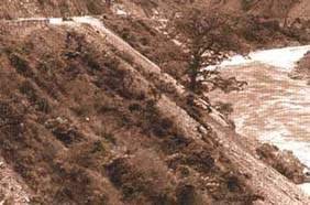
Even on valley alignments, spoil
tipping must be carefully controlled. This debris should have been pushed down
to the river; left like this, it surcharged the slope and contributed to a
slide
You can minimise spoil problems by taking two steps. The first
is to identify those operations that will generate spoil, the places where it
will be generated and the quantities involved, no matter how small. The second
is to plan for its disposal by designating safe tipping sites.
You are responsible for designating suitable sites, and your
criteria for their selection should aim to avoid the problems listed above. When
construction is being undertaken through a conventional construction contract,
you should ensure that both the contractor and the construction workforce are
aware of the restrictions on the disposal of spoil, the location of approved
spoil disposal sites and specific requirements for the management of these
sites. Strictly enforce contract specifications regarding spoil disposal.
You may choose either to discard spoil, or to turn it into
landfill. Observe the following guidelines:
· when you are
creating a landfill site, make maximum use of terraces, level ground and spurs;
· if spoil tipping has to be
done on steep slopes, select areas formed in resistant bedrock. Tipping should
result in no more than the removal of vegetation and shallow soil, with
negligible slope incision thereafter. Bitumen drum disposal chutes can be used
to convey the spoil down a short slope to a safe site below;
· build many small spoil benches
rather than a few large ones, to avoid slope overloading;
· provide a drainage blanket
beneath a spoil bench where there is any indication of a spring seepage at or
near the spoil site;
· compact spoil benches during
construction. While benches cannot be compacted in the formal sense, you can
construct them in definite lifts normally not more than 0.5 m thick, with the
top surface of each lift approximately horizontal. This will allow machines
involved in spreading the spoil to track the surface and provide some degree of
compaction;
· where spoil benches are
constructed on agricultural land, form the tip into a benched profile so that it
can eventually be returned to agricultural production. In the meantime, the
risers between levels must be protected against erosion by applying vegetation
or constructing dry stone walls;
· where the top surface of the
bench is large, reduce runoff by providing regular shallow interceptor drains.
The slope of these drains should be constant as far as is practicable and should
not be so steep as to induce erosion;
· on completion, leave spoil
benches in their required shape and plant them with grasses, shrubs and trees to
encourage maximum stability and resistance to erosion.
Do not permit the following:
· tipping of spoil
into stream channels other than major rivers, as the increased sediment load
will lead to scour and siltation downstream;
· tipping of spoil on to slopes
where road alignments, housing areas or farmland downslope might be affected;
· use of areas of past or active
instability and erosion as tip sites, unless they are at least 50 metres from
the road;
· the discharge of runoff over
the loose front edge of a tip bench during or after construction;
· tipping of spoil in front of
road retaining walls, where impeded drainage could soften the wall
foundation.
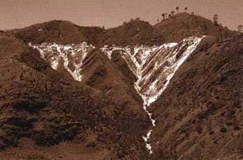
Careless spoil disposal on long,
steep slopes can cause very extensive damage
Figure 1.15: Checklist to assess the quality of
bio-engineering site works
|
TYPE OF WORKS |
SIGNS OF GOOD WORKS |
|
Individual plants |
A bright, healthy colour. |
|
Showing no signs of wilting. |
|
Well proportioned (i.e. not stunted or very tall and
thin). |
|
Crowing fast, with a number of long new shoots. |
|
Without signs of discoloration on the leaves. |
|
Without signs of insect attack on the leaves or shoots
(e.g. holes eaten in the leaves). |
|
Without any obvious signs of disease. |
|
Undamaged. |
|
Not yellowed, except in the later part of the dry season. |
|
Whole sites |
Completely treated, with no gaps or areas missed out. |
|
Evenly covered. |
|
Fully tidied up, with no loose debris on the slope. |
|
Showing no signs of instability. |
|
Stable enough to survive the early rains while plants get
established. |
|
Generally looking good, complete and healthy throughout. |
|
Grass lines |
Complete, with plants at the spacing specified within the rows.
|
|
The right distance between the rows, according to specification.
|
|
Even, with no gaps or poor plants in them. |
|
Straight, according to specification. |
|
Brush layers and palisades |
Complete, with the right number of cuttings per running metre.
|
|
The right distance between the lines, according to
specification. |
|
Even, with no gaps or dead cuttings. |
|
Straight, according to specification. |
|
Fascines
(minor excavations needed to check) |
Complete, with the right number of cuttings per running metre.
|
|
The right distance between lines, according to specification.
|
|
Straight, according to specification. |
Step 16: Implement the civil engineering works

Dressing stone during the
construction of dry stone dentition
Civil engineering works must be completed before the start of
the rainy season. This usually disrupts work seriously from Jestha (May-June)
onwards. Hence the calendar in Figure 1.4 (step 15) suggests carrying out site
preparation works in Magh (January-February), and implementing the civil
engineering works between Falgun and Baisakh (mid February to mid May).
All works must be carried out to a high standard. For this it is
necessary to ensure that adequate site supervision and monitoring are
provided.
Step 17: Implement the bio-engineering works
The actual implementation of bio-engineering site works normally
begins in Ashad (late June). However, this depends on the onset of reliable
monsoon rains. In the east of Nepal it may be slightly earlier, perhaps even in
Jestha; and in the far west a little later, perhaps not until the second half of
Ashad. The start should usually coincide with the time when farmers start to
plant rice on non-irrigated khet land in the local area.
As usual, it is necessary to provide adequate site supervision
to ensure that the works are carried out to the highest possible standard.
Section 3 gives the construction steps for all bio-engineering
techniques.
Step 18: Monitor the works
Check that the works have been completed to a high standard on
the site. Figure 1.15 gives a simple checklist for assessing the quality of
bio-engineering works. It is not fully comprehensive, but gives the main
indicators to look for.
If the plants are being attacked by animals, or are likely to
be, provide protection. Move on to step 19 to plan the maintenance inputs
required by each site.

Grass planting on an eroded
landslide scar. The supervisor is monitoring the works
closely
Step 19: Maintain the works
The maintenance of bio-engineering sites is part of roadside
support maintenance. This is split between routine and
preventative maintenance activities.
The maintenance of roadside vegetation should be planned to
ensure that maximum benefit is attained from the existing infrastructure. Most
maintenance activities have to be carried out at a specific time of year. You
should consider each site independently because maintenance interventions are
site-specific for each slope in each roadside area.
In order to plan roadside support maintenance carefully, it is
necessary to follow these steps.
(a) Devise a schedule of checks for all roadside
support maintenance activities (i.e. list the maintenance tasks and the
intervention times).
(b) Devise a schedule of sites for each check.
(c) Carry out the checks punctually at the allotted times for
every selected area.
(d) Monitor the programme to ensure that the maintenance takes
place as required.
The calendar in Figure 1.16 summarises the timing for the
recommended bio-engineering maintenance operations. (Full details of
bio-engineering maintenance are given in Section 5.)
WHERE TO FIND MORE INFORMATION
In this site handbook, more information is given on each step.
However, because of the large amount of information, the handbook is split up
into a series of technical sections from this point on. The main sections are as
follows.
Section 2 Civil engineering techniques: design features of the
main civil engineering works and construction details of the smaller scale
techniques not covered by other manuals.
Section 3 Bio-engineering techniques: construction details of
all the bio-engineering techniques used by the Department of Roads.
Section 4 Plant production and nurseries: full practical
information about the propagation of plants for bio-engineering and the
management of nurseries.
Section 5 Maintenance of bio-engineering sites: practical
guidelines on every maintenance task under routine and preventative off-road (or
roadside support) maintenance related to vegetation.
In addition, the Reference Manual contains a great deal
of supporting information.
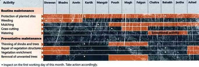
Figure 1.16: Calendar of
bio-engineering maintenance
operations
