3. Preparation for milling offset faces
The following sequence of operations is necessary in order to
prepare the milling of offset faces:
- conceptual planning of the sequence of operations
for milling offset faces
- selecting the milling machine to be used
- choosing the milling and clamping tools, equally the measuring
and testing means
- making available the necessary tools and auxiliaries heeding
the essential aspects of orderly arrangement
- providing the necessary means for adhering to labour safety
requirements (gloves, protective goggles, chip catch, hand brush and rags)
- determine or calculate the cutting values (rotational speed of
the milling spindle, rate of feed, number of runs for each workpiece, rough and
final milling)
- ensure proper functionality and operating safety of the
milling machine, tools and auxiliaries to be used prior to commencing work. Worn
tools should be discarded and replaced. Oil level control and milling machine
lubrication should be undertaken in accordance with the applicable lubrication
instructions.
Clamping workpieces for milling offset faces
Various clamping possibilities exist for milling offset faces of
workpieces. The selection of the appropriate clamping means depends on:
- the geometrical shape and size (length, width and
height) of the workpiece
- the position of the workpiece offset faces to be turned out
- the accuracy requirements in respect of the offset faces
(dimensions, shape and positional deviations)
- the number of workpieces to be processed (single units: small,
medium or large batch series)
- the type of milling machines available (horizontal or vertical
milling machine, portal or two spindle milling machine)
- the available workpiece clamping means and auxiliaries (vice,
clamping square, knee, clamping elements)
The most frequently employed workpiece clamping means for
milling offset faces are:
- clamping in a vice
- clamping directly to the
machine table and
- clamping in devices
Workpieces are generally clamped as single items. The adoption
of multi-piece chucking depends on:
- the geometrical shape and size of the workpieces
to be clamped
- the accuracy requirements in respect of the offset faces
-
the number of workpieces to be processed and
- the existing clamping
possibilities.
When clamping workpieces, ensure that beforehand the burr is
removed and the clamping faces (bearing and supporting surfaces) are cleaned.
The clamping tool must be in proper functional order. Metal chips on the
workpiece faces or burrs on the already processed faces lead to
- top surface impairment (dents or imprints)
and
- workpiece measurement and positional deviations. There is also the
danger of injury!
In order to attain the accuracy parameters as set out in the
work assignment one must pay considerable attention to positional determination
and stability (workpiece supporting and bearing surfaces and clamping force). In
the case of accuracy requirements (angularity and parallelism) less than 0.05 mm
for the offset faces the clamping means for the workpiece should be aligned
using a dial gauge.
Always wear protective gloves when handling
sharp-edged workpieces in order to avoid hand injuries through cuts. Workpiece
deburring should only be undertaken with sound files (snugly fitting file
handles).
- When clamping workplaces in a machine vice
ensure that the height of the workpiece base (parallel pieces) is so selected
that the vice jaws are not deformed once the offset faces have attained the
required "depth".
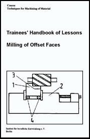
Figure 3 - Workpiece in the machine
vice
1 - workpiece,
2 - machine vice,
3 - distance
between the vice jaws and the milling tool, parallel pieces
As the vice jaws are generally tempered (hardened), any contact
(initial milling) with milling tools would immediately make them useless.
Furthermore, the following factors must be heeded for ensuring
adherence to the accuracy requirements when clamping the work-pieces:
- the angularity and parallelism of the offset faces
depends on a clean workpiece bearing and support.
- the angularity and parallelism of the offset faces depends on
the precise positional determination of the workpiece clamping means and the
workpiece.
- the quality (surface finish) of the offset faces depends on
the condition of the milling tools (sharp or worn), the selection of cutting
values (rotational speed, rate of feed, milling depth) and on the soundness of
the used milling machine (bearing distance of the milling spindle and the
slideways in X-Y-Z direction).
When clamping workpiece directly to the machine table the
following preconditions must be met:
- clean workpiece bearing and support surfaces
- positional determination of the workpiece in accordance with
accuracy requirements (workpiece to be aligned directly to the stop strip or
tongues)
- ensure that the workpiece is so positioned that undesired
positional deviations are not possible (use of a commensurate number of
workpiece clamping elements, a longitudinal stop and suitable pressure pieces,
equally the necessary clamping force).
Figure 4 - Workpiece clamped on the
milling table
1 - workpiece (front view)
2 - milling tool
3
- tongues
4 - stop piece
5 - pressure blocks
6 - feed direction
7 -
clamp
Heed the following when clamping workpieces in a clamping
device:
- clean device supporting surface on the machine
table
- clean workpiece supporting and bearing surfaces (positional
determination on the device)
- utilising all provided clamping elements with
the commensurate clamping force
- determine the milling direction according
to the longitudinal stop of the device
- only use properly functioning and
tested devices.
When clamping the workpieces for simultaneous milling of
offset faces on a portal milling machine, a two-spindle milling machine or when
using gang cutters on a horizontal milling machine ensure the following:
- cleanliness when clamping the workpieces
-
positional determination according to required accuracy parameters
-
positional stability irrespective of the type of workpiece clamping means
-
selection of cutting values according to type of material and the nature of the
milling tool.
The requirements in respect of labour safety must always be
heeded irrespective of the type of clamping means used when milling offset faces
or the manner in which offset faces are turned out.
In order to avoid eye injuries ensure that the
milling protective devices or chip catch are purposefully employed. Workpieces
with burr or sharp-edged faces should only be moved wearing protective gloves or
using rags in order to avoid hand injuries.
How can workpiece and workpiece clamping means with greater
accuracy requirements be
aligned?
________________________________________________________________________________________________________________________________________________________________
What must always be heeded when clamping workpieces in order to
avoid quality
impairment?
________________________________________________________________________________________________________________________________________________________________________________________________________________________________________________
Clamping tools for milling offset faces
The clamping tools must be clamped safety and soundly
(vibration-free). When clamping milling tools it is essential to heed all
cleanliness requirements. Soiling of the bearing surfaces or in between the
milling machine arbor collars adversely affect tensioning through deviations in
true and scheduled running. Only long milling arbors should be used on the
horizontal milling machine. When milling on the vertical milling machine, only
use short milling arbors if possible. In this case the mill can be clamped
directly to the milling spindle.
Selection and use of measuring and testing means
The following measuring and testing means are required for
controlling adherence to accuracy requirements, namely:
- vernier caliper/external micrometer
- depth
vernier caliper/depth micrometer
- bevelled edge square or try square
-
extended limit gauge
The above items should be checked for sound working order and
positioned in readiness.
The service life of measuring and testing means depends to a
considerable extent on their proper usage. This denotes an extension of the time
period during which the measuring result is not adversely affected by
prematurely worn measuring and testing means.
Only thoroughly deburred and clean workpieces should
be
checked.