Back to Home
Page of CD3WD Project or Back to list of CD3WD Publications
 |  |  | Treatment of Lines for Mobile Devices and Appliances - Course: Basic skills and knowledge of electrical engineering. Trainees' handbook of lessons (Institut für Berufliche Entwicklung, 21 p.) |  |  | 2. Treatment of Lines for Mobile Devices and Appliances | |  | 2.1. Removing of Insulations | | | 2.2. Preparation of the Conductors for Further Processing |
|
Treatment of Lines for Mobile Devices and Appliances - Course: Basic skills and knowledge of electrical engineering. Trainees' handbook of lessons (Institut für Berufliche Entwicklung, 21 p.)
2. Treatment of Lines for Mobile Devices and Appliances
2.1. Removing of Insulations
For removing the insulation, the following tools may be used as
auxiliary means:
- Cable strippers
- Automatic deinsulating
tongs
- Thermal deinsulating device
- Deinsulating fixtures
Removing the sheath insulation
- Cutting the rubber sheath in between the cores
until it can be taken hold of by hand.
- Ripping the rubber sheath apart up
to the given measure.
- Cutting the sheath insulation carefully all
around.

Figure 6 Stripping of a light
rubber hose cable
1 notching the rubber coating between the cores,
2
thearing the rubber sheath apart,
3 cutting off the sheath insulation
carefully
Make sure that the core insulation is not cut when
removing the sheath insulation!
Removing the core insulation
- By the cable stripper
. Cutting off one half of the insulation
by a longitudinal cut by the knife (stripping off).
. Cutting off the second
half by a longitudinal cut, too.

Figure 7 Stripping the core
insulation by the electrician's knife
Pay attention to the correct handling of the knife, because the
fine-wire conductor might be damaged by a wrong touch of the knife and break in
the course of further working.
- By the deinsulating tongs
. With movable deinsulating edges, these
are adapted to the cross-section of the conductor.
. The conductor is put
into the pair of jaws of the deinsulating tongs and the tongs are
actuated.
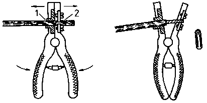
Figure 8 Stripping the core
insulation off with the help of the wire strippers
1 clamping jaw,
2 stripping jaw

Figure 9 Wire strippers
1 cutting edge for various diameters,
2 clamping
jaw,
3 conductor
Do only use the cutting edge assigned to the
cross-section of the conductor and marked accordingly. Conductor cross-sections
exceeding 6 mm2 are deinsulated by the cable stripper.
By the thermal deinsulating device
- Switching the device on.
- Cleaning the
resistance wire curl.
- Selection of temperature. (Core insulation must only
melt, not burn.)
- Removing the core insulation by the deinsulating handle of
the device.
- Switching the device off and pulling the plug after
use.
The core insulation of heat-proof
silicone and rubber-covered cables is not removed by thermal deinsulating
devices due to their heat resistance and the strong smell that would develop.
Make sure that the ends of the conductors are always cleanly
deinsulated. The conductor must neither show rests of the insulation nor
indentations.
Removal of yarn wrappings from cables
- Cutting the yarn wrapping open.
- Prevent the
yarn wrapping from undoing by ligaturing.
- Cutting the yarn wrapping open
and removing it.
- Proceed as described
above.
2.2. Preparation of the Conductors for Further Processing
Why must mobile cables get a special treatment before being
connected?
__________________________________________________
What operations have to be done before the cable is connected?
__________________________________________________
For
- cleaning the conductor
- tinning the
conductor
- soldering on of cable eyes
- pressing on of cable
eyes
the handbook of "Making Permanent Joints" should be used.
After cleaning - also of the internal layers - the
end of the conductor must be accurately retwisted clockwisely.
Tinning of cables and the use of sweating thimbles has to be
avoided to the farest possible extent.
These methods should be applied only in special cases, for
instance if and when eyes must be bent or pressing cable thimbles cannot be
used.
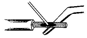
Figure 10 Tinning of a
conductor
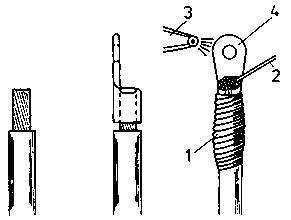
Figure 11 Soldering of a cable
eye
1 fire-resistant wrapping,
2 tin-base
solder,
3 nozzle of the sounder,
4 cable eye
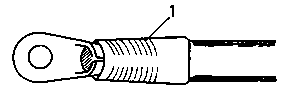
Figure 12 Cable eye soldered
on
1 plastic hose or tape
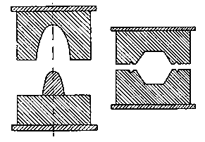
Figure 13 Pressing inserts for
V-shaped grooving or hexagonal pressing
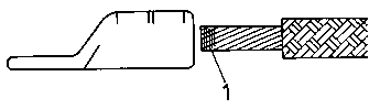
Figure 14 Putting a shaped
conductor into the cable eye
1 binding for aerial line
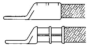
Figure 15 Cable eye before and
after the pressing operation
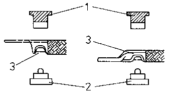
Figure 16 Making the V-shaped
grooving at the top and bottom side of the cable eye
1 top pressing insert,
2 bottom side pressing
insert,
3 V-shaped grooving (left: D-shape, right: C-shape of the
cable eye)
Bending of eyes
- Twisting of the cleaned appropriately prepared
core.
- Bending the eye with the help of an arbor or round-nose pliers.
or
- Dividing the conductor and twisting it separately.
- Putting it
around an arbor from both sides and joining the two ends by twisting them
together.
When bending eyes, make sure that the internal
diameter of the eye is 0.1 to 0.2 mm greater than the diameter of the locking
screw or bolt.
Figure 17 Bending of eyes
1 twisting of the cleaned conductor,
2 eye bent
over an arbor,
3 completed eyes after the conductor having been
divided up and twisted separately
After this, the end of the conductor and the eye are tinned by
soldering iron tin bath.
- If the twisted conductors are tinned first, they
have to be shaped to an eye by round-nose pliers afterwards.
When tinned in a tin bath, the prepared and
flux-coated end of the conductor is dipped into the fluid tin to approximately
3/4 of its lengths.
The process of tin-coating is completed, if and when
the end of the conductor and the eye have a uniform, tin-covered
surface.
Putting on of conductor end sleeves and contact eyes
- If not other forms are required, this technique
should be preferred.
- It can be used with cross-sections up to 16
mm2.
What are the advantages of this technique compared with
tin-coating?
__________________________________________________
Sequence of operations for working conductor end sleeves
- The wires are stripped.
- The wide end of the sleeve is shoved on the blank end of the
conductor.
- The end of the conductor together with the conductor end
sleeve is put into the clamping fixture.
- Clamping by fastening the clamping screw by the required
contact pressure.
Special fields of use of conductor end sleeves
- At terminal points with two cables, one conductor
end sleeve of the appropriate size can be drawn over the two wires.
- Circuit bridges which must not be broken when being
disconnected can be twisted and provided with a conductor end sleeve.
- Conductor of less than 0.75 mm2 in cross-section
are stripped over such length that they can be folded up two or three times and
then put into a conductor end sleeve of a corresponding size.
- Size conductor end sleeves and contact eyes are not marked,
attention must be payed that the conductor cross-sections and the end sleeves
are fitting together.
Assignment of conductor end sleeves to the conductor
cross-sections
(Cross-sections indicated in mm2, main dimensions and
length in mm)
|
Conductor
cross-section |
Conductor
end sleeve |
Main dimension |
Length |
|
|
Internal diameter |
External diameter |
|
|
0.5 |
1.3 |
1.3 |
1.8 |
12 |
|
0.75 |
1.3 |
1.3 |
1.8 |
12 |
|
1.0 |
1.5 |
1.5 |
2.2 |
12 |
|
1.5 |
1.8 |
1.8 |
2.6 |
12 |
|
2.5 |
2.2 |
2.2 |
3.4 |
12 |
|
4.0 |
2.9 |
2.9 |
4.1 |
12 |
|
6.0 |
3.5 |
3.5 |
4.8 |
16 |
|
10.0 |
4.4 |
4.4 |
5.7 |
16 |
|
16.0 |
.5.5 |
5.5 |
6.8 |
16 |
Sequence of operations with the use of contact eyes
- Stripping the wire.
- Prebending the stripped
conductor over an arbor.
- Pressing the contact eye on the prepared
conductor.
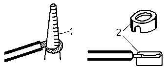
Figure 18 Prebending of the
conductor over an arbor
1 arbor, 2 contact eye
- Putting the conductor with the contact eye in the
mould of the pressing device or in the pressing pliers.
The conductor must be placed into the slot of the
contact eye and in the slot of the matrix of the pressing device.
- Pressing on by pressing device or pressing
pliers.
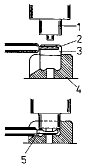
Figure 19 Principle of the
pressing-on of contact eyes
1 punch, 2 conductor, 3 contact eye, 4 matrix, 5 contact eye
with conductor after having been pressed in the matrix

Figure 20 Pressing-on of
contact eyes by the pressing tongs
1 completed contact eye
All individual wires of the flexible conductor must
be held by the sleeve or by the eye.
Why should to cables, which shall be connected to mobile
equipment, preferably conductor end sleeves and contact eyes be attached or
cable eyes be pressed on?
__________________________________________________


