The area within which magnetic actions arise is called the magnetic field.
Field lines are employed to display graphically magnetic fields. Figure 1 shows a current-carrying conductor. Iron powder scattered at the level of this arrangement falls into concentric circles. This leads to a model presentation of field lines.
Figure 1 - Magnetic field and field
line sequence made visible by iron
powder
Bodies of ferromagnetic materials (e.g. iron, nickel, cobalt, etc.) have a magnetic field in their vicinity.
Figure 2 - Magnetic field of a
permanent magnet
Direction of field lines
As indicated in Figure 2 the field lines emerge from the north pole and enter the south pole. Inside the magnet the field lines run from the south to the north pole.
Magnetic poles always arise pairwise.
Magnetic force action law - magnets interact with each other.
Figure 3 - Force actions between
magnets (attraction)
Figure 4 - Force actions between
magnets (repulsion).
1 Force actionOpposite poles attract each other, similar poles repel each other.
Presentation of the magnetic field
Figure 5 presents the magnetic field of a current-carrying conductor.
Figure 5 - Magnetic field of a
current-carrying conductor.
1 Current flow direction
Stipulations for current presentation
- Where the current flows away from the viewer, that is to say into the paper plane, a cross is indicated in the conductor cross-section.
- Where the current flows towards the viewer, that is to say out of the paper plane, a dot is entered into the conductor cross-section.
Figure 6 - Current direction
designation in the plane of field lines
Direction of field lines
As Figure 6 indicates the direction of the magnetic field lines depends on the current direction. If one views the conductor cross-section in current direction, then the field lines appear clockwise.
If one clamps such a current-carrying conductor with one’s fist so that the projecting thumb points in current direction, then the bent fingers indicate the direction of the field lines.
Magnetic poles
A coil comprises several conductor loops. The overall magnetic field is derived from the magnetic fields of the individual conductors.
A current-carrying coil has both a north and south pole.
Figure 7 - Magnetic field of a
current-carrying coil
(1) Magnetic field of a conductor loop
(2) Magnetic field of a coil
1 Slant image
2 Top view as seen from above
Field direction
The magnetic field lines emerge from the north pole and enter the south pole.
If one clamps such a current-carrying coil with one’s right fist so that the bent fingers point in current direction, then the projecting thumb points towards the north pole. (clockhand principle)
Figure 8 - Magnetic field of a coil
and clockhand principle
(1) Coil
(2) Clockhand principle
Field types
Every rotating machine consists of a stationary section (stand) and a rotating section (rotor).
Stands and rotors are made up of magnetic materials and windings and generate magnetic fields in the air gap.
We differentiate between the following magnetic fields:
- constant field
- alternating field
- rotating field
Constant field
A constant field results from a permanent magnet or through a coil saturated by direct current.
Figure 9 - Constant field
(1) Rotor excitation through current flow
(2) Stator excitation through current flow
1 Field winding, 2 Rotor, 3 Magnetic flow, 4 Stator
A constant field denotes a temporally constant magnetic field in an air gap.
Alternating field
An alternating field is generated as alternating current passes through a winding.
A magnetic field which changes its size and direction according to the frequency is called an alternating field.
Figure 10 - Magnetic alternating
field
1 Alternating current, 2 Induction and current, 3 Induction sequence, 4 Current sequence
Rotating field
Definition of term:
A rotating field may be compared to the magnetic field of a rotating, permanent magnet.
Figure 11 - Emergence of a rotating
field through rotation of a permanent magnet
A rotating field denotes a rotating magnetic field within a specific space.
Generating a rotating field:
As Figure 12 indicates, the simplest stator of a rotating machine features three spatially positioned coils at 120 degrees. These coils are saturated by three temporally displaced three-phase currents at 120 degrees.
Figure 12 - Emergence of a rotating
field in the stator of a rotating electrical machine
(1) Stator with three spatially displaced windings
(2) Commensurate temporally shifted currents, t1; t2; t3 Instantaneous times
The current directions are arbitrarily indicated thus:
Figure 13 - Explanation for the
emergence of a rotating field, t1; t2; t3
Instantaneous times
Figure 13 indicates clearly that a single magnetic field emerges with a north and south pole following the spatial displacement of the coils (motionless in the area) coupled with a temporal displacement of the currents.
Speed of the rotating field:
A stator winding where the three coils have been so switched as to only yield one north pole and one south pole is called a two pole machine or a machine with a pole pair (p = 1). A four pole machine thus has two pole pairs etc.
Figure 14 - Four-pole machine
Given a two pole machine the rotating field runs once through for every period of the alternating current. Following a period the pole pairs only undertake a half rotation.
The speed of the rotating field depends on the frequency of the alternating current and the pole pair:
A maximum speed of 3000 rpm can be attained given a frequency of f = 50 Hz.
Magnetic fields are caused by electric currents.
Magnetomotive force signifies the existence of a magnetic field if the current flows through a conductor loop.
Figure 15 - Stationary induction
(1) Current-carrying conductor loop
(2) Current-carrying coil
1 Current flow direction
The current “magnetomotives” the enclosed magnetic field lines. The magnetomotive force can be increased if the same current is conducted several times through the field lines (Cp. Fig. 15). This applies for a current-carrying coil with a number of turns equalling N:
Q = I · N
Formula sign Q
Unit:
(Theta)
[Q] =
1A
Magnetic flow denotes the total number of field lines of a current-carrying coil or a magnet.
Formula sign F
Unit:
weber
F = V ·
s = 1
volt-second
Magnetic flow density denotes the magnetic flow which permeates a certain surface in a vertical direction.
Figure 16 - Definition of magnetic
flow density
1 Surface element, e.g. 1 cm2
A uniform magnetic field is:
Formula sign B
Unit: tesla

Operating principle
A current-carrying conductor is enclosed by a magnetic field. If this conductor is entered into a magnetic field, the individual fields are superimposed.
Figure 17 - Force actions of
current-carrying conductors in the magnetic field
(1) Basic presentation of the superimposing fields
(2) Force action of the superimposed fields
1 Force direction
On the one hand there is magnetic flow boosting. Conversely, one encounters magnetic flow fading.
A current-carrying conductor is pushed away from the external magnetic field towards the weaker field side.
Left hand rule (motor rule)
If the left hand is positioned thus in a magnetic field so that the field lines enter the palm of the hand and the projected four fingers are directed towards the conductor current, then the extended thumb points in force direction towards the conductor.
Figure 18 - Left-hand rule (motor
rule)
1 Current direction in conductor
2 Direction of the magnetic field
3 Direction of movement
Electrodynamic law of force
Force is yielded through the following equation:
F = B · l · I · N
|
F |
force |
|
B |
magnetic flow density of the external magnetic field |
|
I |
current in the conductor |
|
l |
conductor length in the magnetic field |
|
N |
number of conductors in series circuit (coils) |
Motor principle
As opposed to Figure 17, Figure 19 features a conductor loop is positioned in a rotatable manner. A force is exerted on both conductor sides. This yields an overall torque.
M = 2 · F · r
Figure 19 - Torque incidence in a
conductor loop
1 Radius, 2 Effective length, 3 Current direction, 4 Force action
Motor equation
The following equation is forthcoming from the electrodynamic law of force
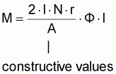
M = 2 · B · l · I · N · r


M = c · F · I
|
c |
machine constants (constructive values) |
| |
magnetic flow of the external magnetic field |
|
I |
current in the conductor loop or coil |
A voltage is induced where a circuit is saturated through a temporally altering magnetic flow.

Given stationary induction (Figure 15), the magnetic flow alteration is generated by means of a stationary conductor loop or coil and a temporally changeable magnetic flow.
Operating principle
Given motional induction a change in the magnetic flow is attained through the movement of magnets, equally through the motion of an electric conductor within a magnetic field.
Figure 20 - Induction through
magnetic flow change (movement of a magnet)
1 Induced current, 2 Direction of movement
Figure 21 - Induction through
magnetic flow change (movement of a conductor)
1 Induced current, 2 Direction of movement
The following applies to several series switched conductors (coils):
U0 = N · B · l · v
|
U0 |
general voltage of a motional conductor in a magnetic field |
|
B |
magnetic flow density of a magnetic field |
|
l |
conductor length in the magnetic field |
|
v |
motional speed of the conductor |
|
N |
number of series switched conductors |
Right hand rule (generator rule)
If the right hand is so positioned in a magnetic field that the field lines enter the open palm of the hand and the projected thumb points in the motional direction of the conductor, then the extended four fingers point in the direction of the current in the conductor loop forthcoming through the generated voltage.
Figure 22 - Right-hand rule
(generator rule)
1 Direction of the magnetic field
2 Direction of the induction current
3 Direction of movement
An example is indicated in Figure 23.
Figure 23 - Rotating movement of a
conductor loop in the magnetic field
Generator equation
The following equation results from applying the induction law:

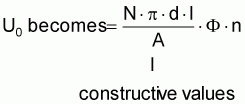
with v = p · d · n

U0 = c · F · n
|
c |
machine constant (constructive values) |
|
n |
speed of the conductor loop |
Questions for repetition and control
1. What causes a magnetic field?
2. How is a magnetic field presented?
3. How are field line direction and current direction related to one another?
4. What are the differences between a magnetic constant field and an alternating field?
5. How is a rotating field generated?
6. What does the speed of the rotating field depend on?
7. What is meant by magnetomotive force?
8. How are magnetic flow and magnetic flow density interrelated?
9. How are the forces directed which similar and opposite magnetic poles exert to one another?
10. Describe the left hand rule.
11. Which values exert an influence on the torque of a motor?
12. Describe the right hand rule.
13. Which values are of decisive importance for the induced voltage in a generator?