| Engines for Biogas (GTZ, 1988, 133 p.) | ||||
| 8. Utilization of the engine's ''Waste'' heat | ||||
| (introduction...) | ||||
| 8.1 Theoretical aspects | ||||
| 8.2 Technical aspects | ||||
|
| |||||||||||||||||||||||||
(Cogeneration)
The degree of utilization of the energy content of engine fuels for power production alone is fairly low, i.e. between 25% and 35% only. Through cogeneration of power and heat the total utilization degree can be improved to about 85%. This provides an incentive to try and use both forms of energy simultaneously whenever possible.
Not only should the waste heat of an engine be utilized whenever
power production is the initial issue. Especially in cases where biogas is
considered for low temperature heat generation (about 100 °C) an engine
should be introduced. The thermodynamic validity of mechanical power is much
higher than that of low temperature heat.
Any fuel suitable for utilization
in engines has the potential to generate power.
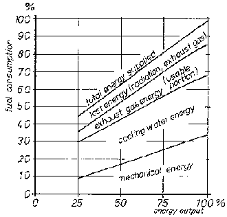
Fig. 8.1: Distribition of fuel energy
in an engine (schematic)
When low temperature heat is required, the degree of utilization (efficiency) of the combustion Process in a boiler is about 85%, hence similar to that of a cogeneration unit:
|
- low temperature |
Using the relations for establishment of the | |
|
heat demand: |
Q = 20 kW fuel consumption and considering power and | |
|
- efficiency of boiler: |
hb = 0.085 |
heat either separately or as a sum for cogeneration: |
|
- mechanical power |
| |
|
demand: |
P = 10 kW | |
|
- efficiency of engine: |
heng = 0.3 |
fc =1/h *(P + Q) x 1/Hu x 3600 |
|
- efficiency of cogeneration: |
hc = 0.85 |
(see Equ. 4.11) |
| |
separate generation of fuel and power |
cogeneration |
|
biogas needed for engine |
fc,e = 6 m³ /h |
- |
|
biogas needed for boiler |
fc,b = 4.2 m³ /h |
- |
|
total biogas needed |
fc,tot = 10.2 m³/h |
fc,tot = 6.4 m³/h |
However the latter can transform one third of the fuel energy into power, a chance that is missed when using a boiler alone.
A simple example shall demonstrate this advantage of a cogeneration unit:
In the case of an optimal matching of heat and power demand in cogeneration the mechanical power of 10 kW is achieved with an additional fuel demand of only 6.4 - 4.2 = 2.2 m³/h. The same power requires 6 m³/h when being produced separately. In other words the efficiency of power production in cogeneration is increased from 30% in separate production to more than 80% in cogeneration. It is understood that demand and supply rarely match so perfectly. But as long as satisfying one type of demand, either power or heat, includes the free benefit of at least partially satisfying the other, it is well worth being considered.
As, however, the demand profiles for power and heat have to be somewhat parallel, continuous operation of the whole system appears to be the most favorable condition for cogeneration in general.
The potential of the engine's heat energy cannot be utilized fully for two reasons:
- The exhaust gas must leave the heat ex- changer at temperatures above 180 °C. Lower temperatures would allow condensation of fuel impurities such as H2S which are corrosive with humidity.
- A certain part of the heat is emitted from the engine housing itself to the surroundings (can be useful to heat the machine room if required).
The diagram in Fig. 8.1 helps to establish the actual quantities of the heat obtainable from the cooling water or air of the engine or the exhaust gas. The respective percentage is multiplied with the engine's total fuel energy consumption as calculated earlier in Chapter 4. As a rough estimation the following relation can also help to establish the total fuel energy input Ef in kJ/s:
Ef = 3 . . .4 x engine operating power (in kW) (Equ. 8.1)
Out of the total energy input the following portions can be utilized as heat (values differ with engine type, size, efficiency, etc. by ± 10%):
- cooling water directly:
35% at temperatures up to 80 °C,
35% at temperatures up to 50 °C,
15% at temperatures up to 200 °C, so that the actual amount of heat obtainable becomes:
Q = proportion x Ef (Equ. 8.2)
whereby: Q = heat flow/transfer in kJ/s.
The temperatures to which the cold flow is actually heated depend on its flow rate. Smaller amounts of water flowing through an exhaust gas heat exchanger will be heated to higher temperatures than a larger water flow. This means that besides the temperatures of the two different media it is also their individual flow rates which determine the amount of heat transferred. The heat increase or decrease of a medium between inlet (1) and outlet (2) of a heat exchanger is given by
Q =m · cp · Dt (in kJ/s) (Equ. 8.3)
whereby: Q = heat decrease/increase (in kJ/s), m = mass flow rate of medium (in kg/s), cp = specific heat of medium (kJ/kg· K)2, Dt = t2 - t1, temperature difference of the medium between inlet and outlet of heat exchanger; positive value indicated heat absorption, negative value heat emission.
The heat exchanger surface A, i.e. the area of the material through which the heat is exchanged from the hot to the cold medium, is established using the heat flow to be utilized, e.g. the actual proportion of the total energy Q as found under Equ. 8.2:
 (Equ. 8.4)
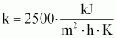
The heat transfer coefficient k depends on the types of media flowing on each side of the separation wall, the flow characteristics, and the wall material itself. Assuming that the wall material is metal (steel, brass, copper, aluminum) and the surfaces clean, the following mean k values can be used considering however that they can differ by + 50%:
- liquid - metal wall - liquid: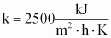
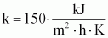
- liquid-metal-gas: k = 150
- gas-metal-gas: k = 80
The liquid is usually water; the gas can be air or exhaust gas.
The active mean temperature difference Dtm varies with the type of heat exchanger but can be established within acceptable tolerances by (see Fig. 8.2):
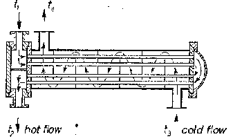
Fig. 8.2: Principial scheme of heat
exchanger (mixed flow type)
Dtm =0.5/(t1 + t2) - (t3-t4)/ (Equ. 8.5)
Counterflow exchanges as in Fig. 8.2) have a higher Dt value, parallel flow a lower value and mixed flow/crossflow types (e.g. vehicle radiators) have roughly the value calculated in Equ. 8.5.
When using the cooling air from an aircooled engine or air emerging from a standard engine radiator, these airflows shall in no way be subjected to resistance in the following heat exchanger nor directly connected to equipment, e.g. dryer. The original blowers are normally too weak to overcome any extra resistance. The cooling of the engine can therefore become insufficient and the engine overheats.
For water heating from exhaust gas a heat exchanger design with two concentric tubes is recommended and is easy to manufacture. For water heating from cooling water a heat exchanger in the form of a coil within a larger vessel or tank is suitable. The coil or other heat exchanger shall not be too long, too narrow or otherwise impose too much resistance to the cooling water flow as the normal water pump is not designed for much extra flow resistance. Here too the cooling of the engine may become insufficient. Larger heat exchangers should be insulated from outside as they emit heat to the surroundings which is lost for the initial purpose.
The operation of the heat exchanger, especially when using the engine's cooling air or water, needs a safety control to ensure that the cooling of the engine is always sufficient and the temperature of the cooling water returning to the engine is at around 50 °C with only minor fluctuations. The amount of heat conducted away from the engine has to match with the amount automatically produced in the engine according to its actual load. If more heat is produced than consumed, the control can be achieved using thermostats and a separate safety bypass cooler. If more heat is consumed from the cooling water than produced, the engine will gradually operate at too low temperatures which increases wear.
Taking too much heat from the exhaust gas reduces the final outlet temperatures and may lead to corrosion in the exhaust gas heat exchanger. The operation of the heat exchangers or heat users must therefore always consider that the heat production in the engine is linked directly to the mechanical power output, i.e. the driven machine's operation. Under the control aspect continuous operation of the whole system is therefore the best precondition for waste heat utilization.
The following example shall demonstrate the layout of a heat exchanger:
Given conditions:
- engine mechanical power: P = 15 kW
- engine efficiency: heng = 0.32
- cooling water temperatures:
from engine: 80 °C, back to engine: 50°C
- exhaust gas temperatures:
- from engine: 350 °C,
to surroundings: 180°C
- cold water temperature: tw = 20 °C
Problem: Supply of as much hot water at 60 °C as possible at constant rate.
Solution: Step 1:
Establish total fuel energy input:
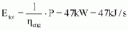 (see Equ. 3.9)
Step 2:
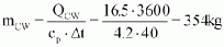
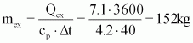
Establish amount of heat to be obtained (see Equ. 8.2):
a) from cooling water
Qcw = 0.35 · 47 = 16.5 kJ/sb) from exhaust gas
Qex = 0.15 · 47 = 7.1 kJ/s
Step 3:
Establish heat exchanger surface size (see Equ. 8.4):
a) cooling water heat exchanger
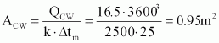
with
- Dtm = 0.5/(80 + 50) - (20 + 60)/ = 25 K4
b) exhaust gas heat exchanger
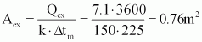
with
- Dtm = 0.5/(350 + 180) - (20 + 60) /= 225 K
The exchanger areas can be materialized with a number of tubes in parallel to prevent excessively long exchangers.
Step 4:
Establish how much hot water is available (see Equ. 8.3):
a) from cooling water exchanger
b) from exhaust gas
with
cp = 4.2 kj/(kg · k)
Dt= 60-20=40K
for the water circuit.
The two heat exchangers produce a total of 506 kg/in (or 1/h) of hot water. The parallel arrangement, i.e. cold water flows to both heat exchangers, allows for more flexibility in the water use:
- When water of higher temperature is wanted, the exhaust gas unit can supply it at a lower water flow rate.
- When less water is used the exhaust gas unit can be reduced to 0 l/h; only the final exhaust gas outlet temperature rises.
- When the warm water demand is further reduced, but the engine continues operation at the same load, part of the heated water from the engine's cooling water exchanger (not the cooling water itself) can be purged off to maintain engine cooling unless the cooling water cycle can be switched over to a bypass cycle with a standard engine radiator cum fan.
Ready-made cogeneration units for supply of heat and electricity are on the market in various sizes and versions. Heat exchangers can also be found in a large variety; some are even supplied for ready mounting to certain engine types. For both see Chapter 10.
