Back to Home
Page of CD3WD Project or Back to list of CD3WD Publications
 |  |  | Introduction of Animal Powered Cereal Mills (GTZ, 1996, 70 p.) |  |  | Part II: Construction of the Animal-Powered Mill | |  | 1. Preface | | | 2. How Efficient is a Draft Animal and how much Power is Required for Driving a Mill? | | | 3. The Frictional Wheel -Principle of the Animal-Powered Mill | | | 4. The Idea and its Realization | | | 5. Functional Structure of the Animal-Powered Mill | | | 6. Construction of the Functional Units | | | 7. Dear Reader... |
|
Introduction of Animal Powered Cereal Mills (GTZ, 1996, 70 p.)
Part II: Construction of the Animal-Powered Mill
1. Preface
The second part of this guide is intended for the technically
proficient reader who considers the animal-powered mill a practicable
alternative to both manual labor and motor-driven mills in his field of
activities, and who wants to test, construct and possibly propagate it. This
construction guide should not be used as a conventional manual. We take the view
that instructions which precisely dictate the arrangement, dimensions and
materials to the reader are not in line with the concept of appropriate
technology. Moreover, they make it impossible for the reader and his co-workers
to contribute their own ideas and experiences and thus help to improve the
device. The development of the animal-powered mill is yet to be completed. There
remains a lot of work to be done before the animal-powered mill, including all
its components, can be constructed in countries which are short in material
supplies, and before it fully satisfies the needs of its users. We would like to
invite the readers of this guide to help us with this work. We do not intend to
offer universal solutions but rather construction examples. The main emphasis
will be put on the explanation of the reasons why we opted for certain
solutions, why other solutions turned out to be less suitable, and why some
components involve specific problems.
This guide is not designed to take away the role of the reader
in constructing his own animal-powered mill. On the contrary' it is our prime
intention to give the reader an incentive to think over his own needs and then
design his own adaptations to specific problems of application. Another purpose
of this guide is to help the reader avoid experiencing difficulties which others
have already
encountered.
2. How Efficient is a Draft Animal and how much Power is Required for Driving a Mill?
Table I surveys the performance of different draft animals. In
view of the fact that the average performance of draft animals can be compared
with the efficiency of electric kitchen appliances, it may seem hardly
understandable that the mastery of the animal tractive power can pose actual
problems for the mechanical engineer. It is, however, necessary to bear in mind
that the maximum tractive power of the animals, which can be maintained for a
very limited time, can be ten times the normal optimum level. Although their
maximum performance is relatively low, they can develop enormous tractive power
because they move very slowly.
The dimensioning of the driving gear of the power gear depends
on the maximum torque the draft animal can exert on the power gear. If the
machine of a traditional toothed power gear without predetermined breaking
points blocks, when driven by an ox of 500 kg, the maximum torque would be
approximately 15 000 Nm, thus corresponding to 15 times the maximum motor torque
of a Peugeot 504 Diesel.
For this reason it is necessary to limit the torque that can act
upon the power gear by means of predetermined breaking points as e.g. shearing
pins or by means of torque limiters such as belt drives or frictional wheels.
On the other hand, the machine - in this case the grinding unit
- must be designed for the average performance of draft animals i.e. for 200 to
500 W because it has to be operated for several hours a day.
In spite of the low efficiency, the daily continuous - operation
requires a solid construction of the grinding unit. During the initial stages of
the project, relatively small grinding units were used which had been designed
for the actuation by means of small motors (3 to 5 cont.hp.) The power required
for driving these mills was reduced by operating them with a lower number of
revolutions (60 to 150 rpm) than originally planned (400 to 600 rpm).
Tab. 1: Tractive power of different draft animals in developing
countries
|
Animal |
Average weight of animal (kg) |
Approx. draft (continuous) (kg) |
Average speed (m/s) |
Power developed (W) |
|
Light horse |
400-700 |
60-80 |
1 |
735 |
|
Bullock |
500-900 |
60-80 |
0.6-0.85 |
550 |
|
Buffalo |
400-900 |
50-80 |
0.8 -0.9 |
340 |
|
Cow |
400-600 |
50-60 |
0.7 |
345 |
|
Mule |
350-500 |
50-60 |
0.9- 1 |
510 |
|
Donkey |
200-300 |
30-40 |
0.7 |
245 |
At the same time, however, the development of a grinding unit
adapted to the power gear began; a grinding unit which, moreover, could be
constructed by local craftsmen.
The construction is determined by the power to be transmitted
and by the ratio of transmission. For the time being, these parameters can only
be calculated roughly. Their actual values differ very much from region to
region depending on the condition of the draft animals, the cereals, and the
desired fineness of the flour. When a power gear is tested in a certain region
for the first time it is always likely that further modifications will be
necessary after the installation.
The power to be transmitted corresponds to the average
performance of the draft animals available in the respective region (see Table
1).
Experience shows that the required speed of the mill varies
between 60 and 150 rpm. For donkeys, a lower value can be assessed, for oxen a
higher one, and for horses a medium
value.
3. The Frictional Wheel -Principle of the Animal-Powered Mill
At first sight the technician might consider a number of
solutions more appropriate than the somewhat unconventional construction
principle of the animal-powered mill (for a more detailed description see
Chapter 3.1 of the first part of this guide). Toothed power gears, rope power
gears, chain power gears (Fig. 1-3) are only a few of the numerous constructions
known in the history of technology.
All the solutions have two things in common:
- due to the high torque exerted by the
animals the machine parts of the first gear stage have to be extremely large and
are therefore expensive.
- the gearing has to be connected by means of
underground shafts and cardan joints.

FIGURE (FIG.1-2)
Fig. 1: A 19th century German toothed power gear
Fig. 2: A
rope power gear patented in Germany in 1882

Fig. 3: A "chain power gear" patented
in the German Reich in 1879
Since high-quality and expensive machine parts must be used,
small farmers in Third World countries cannot afford these animal-powered mills.
Today, a power gear like the one shown in Fig. I would cost as much as a small
car. We take the view that a modern-day comeback of traditional animal powered
mills as shown for instance in Fig. 1 will only make sense if they are already
used widely in the respective area, and if the stone required for the grinding
unit and the necessary know-how for the production of the stones are available
locally. Even in this case it is doubtful whether such a mill would be cheaper
than a mill with small, high- speed grinding stones and a gearing.
In comparison with conventional power gears, the principle of
the "runner wheel power gear" has the following main technical advantages:
- for the often problematic first gear stage of the
power gear, a concrete path that can be easily constructed locally and a
universally available car wheel are used
- since the grinding unit runs round
in a circle with the animal, long subterranean shafts and cardan joints can be
dispensed with
- the frictional wheel principle effectively protects the
power gear as well as the machine against overload.

Fig. 4: Sketch of a traditional
animal-powered mill from Hammamet,
Tunisia
4. The Idea and its Realization
Before going into technical details, we want to give the reader
a first insight into the construction of the animal powered mill and its
specific problems by presenting the "ancestral portrait gallery" of the power
gear.
The idea in the history of technology

Fig. 5: A 19th century runner wheel
power gear patented in Germany in 1888. The wheel was made of steel and ran on a
steel rail. Due to the low friction coefficient of the friction pairing
steel-steel the wheel had to be extremely heavy and was therefore expensive. It
may be presumed that its high price was the reason why this power gear did not
become generally accepted.
in technical cooperation
Further development

Fig. 10: A staff member of the
American organization ATI and Cheikh Gueye have worked out a number of
additional simplifications. which - if they prove their worth in practical
operation - could result in a further considerable reduction of the production
costs. The semicircular harness has been dispensed with. This implies certain
disadvantages (less ideal power transmission more difficult guidance of the
animal). On the other hand it is now possible to replace the rigid frame
construction by a simple pipe (3") since the bending moment acting upon the axle
is lower. Instead of the chain drive a friction roller made of cast iron which
is directly driven by the car wheel is used as a second gear stage. The
construction is presently being tested in Senegal. If it proves its worth in
practical operation, a more ' detailed description will be given in a
supplementary sheet to this
guide.
5. Functional Structure of the Animal-Powered Mill
In order to tackle the construction in a structured manner, a
number of conditions must be established. These conditions must be considered
when dividing the overall function into several partial functions which are then
assigned functional units (Fig. 12, p. 34). Most of the conditions were already
defined in the previous chapters.
The precondition that the animal goes round in a circle might be
considered banal. One could, however, conceive a device whose wheel runs on a
straight path (i.e. a kind of cart whose wheels drive the mill). The most
important advantage of the circular movement is that the animal moves almost
without guidance once it gets used to it. Another advantage of the circular
movement is that there is no loss of time because the animals must not turn
round as is the case with a straight path.
Before a functional principle can be established, first
decisions with regard to the basic construction of the individual functional
units must be made:
Drive mechanism: The car wheel which runs along on a circular
path is the heart of the drive mechanism. The transmission obtained in this way
is, however, not sufficient for driving the mill. A second transmission by means
of a chain, a belt drive, or similar' is essential. The wheel is connected to
the second gear stage by a shaft.
Central axle, frame: The wheel must be guided in a circle. For
this purpose the drive unit is connected to a bearing unit at the central point
of the path by means of a frame, or similar.
Grinding unit: A high-speed,
small-size mill with a grinding mechanism made of stone disks, similar to the
one used with small-power motors, serves as a grinding unit.
The combination of these functional units results in the
functional principle shown in Fig. 11.

Fig. 11: The functional principle of
the animal powered mill

FIGURE 12: Functional diagram of the
animal powered
mill.
6. Construction of the Functional Units
6.1 Harnessing
The harnessing is designed to transmit the tractive power of the
animal with the least possible loss to the power gear. The slightest loss is
attained when the power transmission is
- as tangential as possible and
- as horizontal
as possible.
Tangential power transmission
It is easier for the draft animal to move along a circular track
if the front and hind legs move on the same radius.
Therefore, power transmission will always be subject to losses
of power when transmitted to the power gear behind the animal, since in this
case power transmission at a right angle is impossible (Fig. 14).
For this reason it is advisable to transmit the force to the
power gear between the front and hind legs of the animal (Fig. 15)

Fig. 13: Harnessing

Fig. 14: Power losses occur because
the draft animal is not harnessed at a right angle.
Horizontal power transmission
When a draft animal draws a load under a vertical angle, this
load can be divided into a horizontal tractive load component and a vertical
carrying load component (Fig. 16). When the power gear is in operation the
carrying load component results in a loss in efficiency. After all, the draft
animal is supposed to pull the power gear and not to lift it. The ideal solution
would be to harness the draft animal horizontally to the power gear by means of
a pull rope or a pull chain. This is only possible with horses and donkeys,
because these animals draw mainly with their breasts and shoulders, whereas oxen
and cows draw with their necks. For pressing the yoke onto the necks of the cows
a slightly angular guide of the pull rope or the pull chain is required. With
regard to the size of the angle no definite statement can be made. It should,
however, be as wide as necessary and as small as possible.

Fig. 15:Power losses are avoided by
harnessing the draft animal to a semi-circular harness]

Fig. 16: Vertical and horizontal
components of the tractive power; no power losses occur when the pull chain is
in a horizontal position.

Fig. 17: The semi-circular harness
Construction examples
Most of the power gears that have been constructed so far have a
semi-circular harnessing consisting of two curved pipes (Fig. 17).
The two pipes are welded together in such a way that from above
they look like a trapezoid.
On the outer side of the semi-circular harness
there are hooks at various heights to which the animal's outer pull chain can be
fastened.
It is advisable to construct the harnessing in such a way that
it can be removed after use of the mill. This construction helps to prevent
children playing with the mill and furthermore makes its unauthorized use
impossible. For example, the semi-circular harness may be inserted into two
pipes that are welded to the frame. In this case limit stops must be provided
for at the two inner pipes.
It must be decided from case to case whether such a relatively
costly harness should be used or whether the disadvantages of a more simple
harness, as shown in Fig. 10, p. 32, can be accepted for the sake of cost
saving.
Dimensioning proposal
|
Harness: |
pipe d = 40 mm, s = 3 mm |
|
Harnessing hooks: |
round steel d = 10 - 12 mm |
|
Limit stops: round steel |
d = 10-12 mm |
|
Fastening of the harness to the framepipe |
d = 50 mm, s = 3 mrn |
- The height of the semi-circular harness depends on
the height of the wall, the diameter of the wheel and the height of the draft
animals.
- The width of the semi-circular harness depends on the breadth of
the draft animals.
Construction tips
- To bend the pipes, they are first filled with
sand, then heated and finally curved.
6.2 The path
The main function of the path is to ensure a good power
transmission between the ground and the car wheel. Concrete has proved to be a
good material for this purpose, since the coefficient of friction between
concrete and the car wheel is between 0.85 and 1. For two reasons the path
should be slightly raised:
- to prevent the path from filling with sand and
dirt
- to facilitate a horizontal power transmission
If possible, the power should be transmitted at the height of
the contact surface of the wheel and the path. Otherwise the torque acting upon
the frame could result in a major distortion of the frame.
The height of the path is limited by its costs. The paths of
most animal powered mills constructed so far consist of ringshaped walls made of
two rows of concrete blocks. This corresponds to a height of 40 to 50 cm.
Attempts have been made to cast the entire wall in one concrete block. The
construction of the shuttering, however, turned out to be much more costly and
time-consuming than the construction of the path walls.
The capacity of resistance to wear of conventional concrete
blocks is not sufficient to resist the continual stress caused by the
circulating wheel. Therefore, the wall must be reinforced by a more solid
concrete covering of 5 - 10 cm thickness which must contain more cement and be
mixed with small laterite stones. The laterite stones help considerably to
reduce abrasion. Moreover, the covering should be fortified with concrete
reinforcing round steel.
The construction of the wall is difficult because
a) it has to be almost perfectly round
b) it has
to be almost perfectly level

Fig. 18: The path
Dimensioning proposal
|
Average diameter of the path: |
6 m |
(see also Chapter 6.3)
|
Width of the path: |
at least 25 cm |
|
Height of the path (from ground). |
40 - 50 cm |
|
Height of the foundation: |
5cm |
|
Height of the covering: |
5cm |
|
Ratio of components: |
foundation: 150 kg/m³ |
|
concrete blocks: 110 kg/m³ |
|
covering: 350 kg/m³ |
Construction tips
- Before beginning with the construction, the
central point of the ring should be marked with the help of a concrete
reinforcing round steel of 1 m length. A rope which should be as inflexible as
possible serves as a compass. The excavation required for the foundation is
drawn on the ground with the help of the compass. Later, the rope compass is
used for controlling the position of the concrete blocks.
- A level
foundation of the wall is obtained by driving a concrete reinforcing round steel
into the ground to be excavated at its highest point. 5 cm of the reinforcing
round steel must jut out of the ground. Further reinforcing bars must now be
driven into the ground at 1 m intervals. Each reinforcing bar has to be adjusted
to the previous one with the help of a water balance. The concrete for the
foundation is then filled up to the very top of the concrete reinforcing round
steel.
- An easily removable shuttering for the concrete covering can be
produced with plywood strips 5 - 8 mm thick and 20 cm wide. The plywood strips
are pressed against the wall from the inside as well as from the outside by
means of simple clamps (consisting of concrete reinforcing round steel of 12 -
14 mm thickness. The covering should, however, not be higher than 5 - 8 cm,
because otherwise the shuttering could collapse (Fig. 19).
Potential problems
The concrete path is one of the most expensive component parts
of the animal powered mill.
A reliable but cheaper solution could certainly
be considered as a major contribution to making the device more economical.

Fig. 19: Structure of the path
6.3 The drive unit
The drive unit is designed to transmit the force required for
driving the mill from the draft animal to the mill and at the same time increase
the "number of revolutions" of the draft animal.
The drive mechanism consists
of the following components - a car wheel - a second gear stage (chain, belt
drive, etc.) - a shaft - bearings

Fig. 20: The drive unit
The car wheel
The force that can be transmitted by the car wheel depends on
the coefficient friction between path and wheel and on the load on the wheel.
The maximum peripheral force which can be transmitted by the wheel is
F max = µ x Fg
Fg: weight
µ: coefficient of
friction
(for rubber tires running on concrete µ is 0.85 - 1. On a
dry path a higher coefficient of friction can be achieved with bald tires than
with new ones).
The maximum power that can be transmitted is
Pmax =µ x Fg x d x pi x n/60 x e
e= efficiency of the
power transmission
d = diameter of the wheel (m)
n = revolutions of the
wheel (1/min)
Fg = weight (N)
Losses occur in the first gear stage. Primarily, these losses
are a result of boring friction and rolling resistance.
Boring friction occurs when a cylindrical body (an automobile
tire is a cylindrical body) runs on a circular path. In principle, the tire has
the tendency to run straight ahead. When forced to move on a circular path the
tire runs too slowly on the outer radius of the circular path and too fast on
the inner radius. This relative motion is the reason for increased wear and
power loss.
The wider the tire becomes in relation to the path, the higher
the boring friction. The diameter of the path should therefore be as large as
possible, whereas the width of the tires should be as small as possible.
The rolling resistance is a result of the elastic deformation of
the tires and of the path. For a car wheel loaded with 200 kg which has the
proper tire pressure, the rolling resistance is 30 - 40 N (3-4 kg). By
increasing the tire pressure the rolling resistance can be reduced.
Dimensioning proposal
Size of tire 155 - 13. These tires can be obtained almost
everywhere. Their outside diameter is approximately 60 cm. A transmission ratio
of 1:10 can be achieved with a path diameter of approximately 6 m.
The second gear stage
Assuming that
- a transmission ratio of 1:10 is achieved in the
first gear stage,
- the draft animal walks 2-3 rounds per minute,
- a
speed of 60 - 140 rpm is required to drive the mill, a transmission ratio of 1:3
- 1:7 is needed in the second gear stage.
The structural components of the second gear stage should not
demand a very precise mounting. Taking this into account
- a roller chain gearing - a V-belt drive gearing -
a flat belt drive gearing - or a friction gear in which the car wheel serves as
a driving pulley (see also p. 32, Fig. 10) could be used.
Dimensioning examples:
The power to be transmitted should on
average be 1 kW, the transmission ratio 1:5, and the speed of the driving gear
should be 20 rpm.
Chain drive:
|
chain: |
10 B. 5/8" |
|
|
wheel: |
76 teeth |
d = 391 mm |
|
pinion: |
15 teeth |
d = 83 mm |
Flat belt drive:
|
driving disk: |
d = 500 mm |
|
driven disk: |
d = 100 mm |
|
leather belt: |
belt width approx.200 mm, thickness of belt: 3 mm |
|
synthetic belt: |
belt width approx. 60 mm, thickness of belt: 1.4 mm |
V-belt drive:
|
driving disk: |
500 mm |
|
driven disk: |
100 mm standard V-belt: width 17 mm |
Due to the large belt width which would otherwise be necessary,
a flat belt drive can only be used if high-quality belts are available. With
narrow axle bases and a vertical installation, the required high initial tension
of the belt causes problems. The most important advantage of flat belt drives is
the fact that the pulleys can be produced locally. To prevent wear of the belt
the bearing surface of at least one pulley must have a crowned surface.
The biggest disadvantage of V-belts is the high price of the
pulleys, which can hardly be produced locally (the lathe must have a turning
diameter of 500 mm!). The required V-belts are difficult to obtain in developing
countries.
Roller chains can be bought in almost all developing countries.
Even though the chain wheels can only be produced by extremely gifted craftsmen
or with the help of expensive machine tools, they are cheaper than industrially
manufactured V-belts or flat belt pulleys.
The length of the chain can easily be varied by removing or
adding chain links. Tensioning devices are unnecessary.
For these reasons chain drives were used for the second gear
stage of all animal powered mills that have been installed so far.
Dimensioning proposal
Roller chain 10 B 5/8", wheel 76 teeth If it is the first
installation in a region, it is advisable to keep a number of pinions ready (13,
17, 21, 25 teeth), for adapting the transmission to the performance of the draft
animals and to the required flour fineness.
Bearings and shafts
Fig. 21 shows appropriate and less appropriate arrangements of
the wheel, the bearings and the chain wheel.
The shaft must be capable of resisting and/or transmitting the
following forces and torques:
- the weight of the frame
- the longitudinal
force of the tires - the chain and/or belt forces
- the torque necessary for
driving the mill
The shaft material of most of the so far installed animal
powered mills was bright drawn round steel with a diameter of 40 mm. Bright
drawn material fits if it has a slightly smaller dimension than specified (h 11
- h 8). It need not be turned to size, but it is quite expensive.
The necessity of using bright drawn shafts is primarily a
consequence of the use of ball bearings for the animal powered mills already
installed.
In most cases Y-bearing units have been used so far, They have a
crowned outer ring and can, if necessary, be adjusted in the bearing housing for
compensating alignment errors.
The inner ring has an eccentric ring, headless
pins or an adapter sleeve which serves for pressing the bearing to the shaft.
Self-aligning ball bearings are also available with such mounting devices.

Fig. 21: The most suitable
arrangement of the chain wheel between two bearings
A conventional round steel shaft can of course be used, provided
that a lathe for turning is available.
In this case ordinary deep groove ball bearings can also be used
(press fit indispensable). With deep groove ball bearings a more rapid wear must
be accepted in the case of alignment errors.
Potential problems
The rolling bearings account for a relatively high share of the
total costs of the device. We favored this solution because we wanted to ensure
a high reliability and a high efficiency of the power gear in the introductory
phase. It should be considered whether lower costs would possibly justify a less
complicated bearing construction and a lower efficiency. The use of wood
bearings might, for instance, be an alternative. Wood bearings (Fig. 22) made of
hardwood could easily be produced locally. In order to increase the wear
resistance, the wood bearings should be soaked in hot oil for 24 hours.

Fig. 22:A simple hardwood bearing.
For transmitting the axial forces the shaft must be equipped with a steel disk.

Fig. 23: Hub for mounting the wheel
to the shaft

Fig. 24: The frame
Installation of the drive unit
The easiest way of installing the chain wheel on the shaft is to
install it by means of a headless pin (M 8 or larger). The necessary boring
inside the shaft should fit precisely because otherwise it will widen very soon.
The car wheel is best mounted on the hub of a donkey or ox cart and should be
fastened to the shaft with a bolt. In case there is no hub, it can be
constructed by using sheet steel and a suitable pipe (Fig. 23). The drive unit
and the bearings are fastened to two crossheads of the frame (Fig. 28).
6.4 The frame
The frame has several functions:
- to fasten the drive unit, the grinding unit and
the harnessing
- to carry the seat for the user, so that the user need not go
round in a circle behind the power gear
- to connect the wheel and the
central axle so that the central axle can keep the wheel on its circular
path.
The frame must resist a vertical bending moment which is
primarily produced by the weight of the user. A horizontal bending moment
results from the tractive power of the animal which must be supported by the
central axle. It is, however, the torsional moment that acts upon the with
latticework reinforcement frame via the lever arm of the frame (Fig. 25) which
is of crucial importance for the considerations regarding the stability of the
frame.

Fig. 25: Action of the torsional
moment on the frame

Fig. 26: Power gear frame made of
channel steel
For this reason the torsional resistance of the frame must be as
high as possible.
Construction examples
Channel steel frame with latticework reinforcement
The frame of the first animal powered mills was made of channel
steel. Since channel steel has a relatively low section modulus of torsion, the
frame was rein forced by a latticework construction (Fig. 26)
Frame made from pipes
Later, water pipes were used for the frame construction. Due to
the higher polar section modulus of pipes in comparison with channel steel, the
latticework construction could be dispensed with (Fig. 27). The water pipes can
be replaced by a square tube of a similar dimension. In this way the drive unit,
the grinding unit etc. can be mounted even more easily.
In the final analysis, however, the choice of the materials will
be determined by their costs.
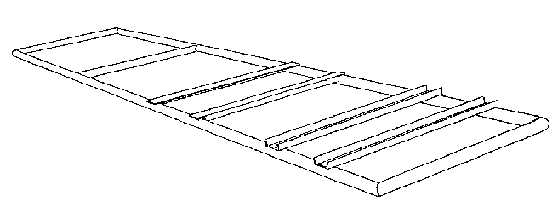
Fig. 27: Pipe construction of the
frame
Arrangement of the grinding unit, the drive unit, the seat and
the holding device for the calabash (Fig. 28)
The height of the table on which the grinding unit is mounted
depends primarily on the required axle base between the two chain wheels. The
axle base should be at least 400 mm.
The table should be very rigid' because the grinding unit must
not vibrate under the influence of the chain forces. Of particular importance is
the reinforcement of the table around the mounting holes for the grinding unit.
The table is only necessary if a separately bought grinding unit is used. If the
grinding unit is produced locally, the table can be integrated into the grinding
unit. It should be made sure that the crossheads for mounting the drive unit are
connected as securely as possible to the frame. The arrangement of the seat and
of the holding device for the calabash should be determined by ergonomic
considerations.
Dimensioning proposal
Frame:
-pipe (round) 60 x 3 or 48 x 4
-square tube 50 x
4
-channel steel U 60 x 6
Latticework reinforcement: round steel (concrete reinforcing
round steel) 12 mm Holding device for the calabash: round steel (concrete
reinforcing round steel) 10 or 12 mm
Crossheads for mounting the bearings: channel steel U 60 x 6
Table for mounting the grinding unit: angle steel L 40 x 3,
sheet metal 3 mm
Seat. angle steel L 40 x 3, sheet metal 2 mm

Fig. 28: Arrangement of the components
on the frame
6.5 The central axle
In order to guide the wheel precisely' the axle must be exactly
central and must be absolutely vertical.
Foundation
The central axle must be connected to a concrete foundation in
the center of the concrete path.
Dimensioning proposal
For saving concrete, a cross-shaped construction of the
foundation has proved to be advantageous. The dimensions are shown in Fig. 30.
Ratio of mixture: 200 kg/m³. The foundation should be fortified by concrete
reinforcing round steel.

Fig. 29: The central axle
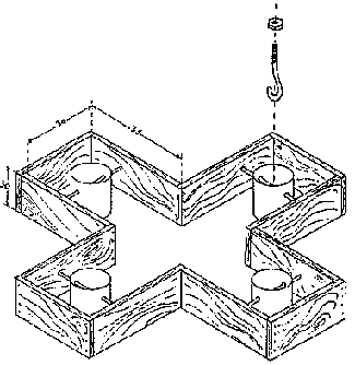
Fig. 30: Shuttering of the foundation
for the central axle with tins for fastening the anchorages
Construction tip
It has turned out to be difficult to embed the bolts for the
attachment of the central axle in the foundation in such an exact manner that
they are all level with the mounting holes in the central axle.
It is therefore advisable to reserve holes for subsequent
filling out. At the bottom of these holes rod irons are anchored in the
concrete. These holes can be produced with the help of tins, polystyrene blocks
or sand-filled plastic bags. Subsequently, the bolts with a hook at one end are
hung in the rod irons (Fig. 30). In this way, the bolts have enough play for
adjusting their position to the mounting holes in the central axle and thus make
a precise alignment of the axle possible. It is advisable to complete the entire
metal structure before completing the foundation. The height of the foundation
can then be adjusted to the dimensions of the animal powered mill (Fig. 31).

Fig. 31: Determination of the
foundation height
Metal construction
The design of the central axle of the animal powered mills
installed so far has often been- modified.
The factors that determine the construction are
- the rigidity of the construction (Considerable
power peaks may occur. The resulting vibrations of the animal powered mill have
a negative effect on the grinding process.)
- saving of material (Due to the
use of roller bearings - as in the case of the drive unit - expensive bright
drawn shaft has up to now been used for the central axle. As a consequence, the
axle must be as short as possible).

Fig. 32: Different constructions of
the central axle
Construction examples
Fig. 32 shows several construction examples
Dimensioning proposals
Cross-shaped foundation: channel steel 60 x
6
Axle: bright drawn shaft d = 40 mm
Reinforcements: sheet metal 3
mm
Attachment of the frame: channel steel 100 x 6
Hub: channel steel 60 x
6 or pipe 80 x 5 and channel steel 80 x 6
In order to compensate possible inaccuracies of the path and the
central axle, the frame of the animal powered mills constructed so far was
mounted to the central axle in a vertically flexible installation. Initially,
wood bearings were used for this purpose. Practice has shown, however, that the
excursions are so negligible that it is sufficient mount the frame direct on
rubber plates or rubber strips (Fig. 33).

Fig. 33: Coupling of the frame to the
central axle
Potential problems
Up to now, rolling bearings have been used for the central axle
and driving shaft. As to the possibility of replacing the rolling bearings with
wood bearings, see also Chapter 5. Due to the lower forces and the lower speed
of the central axle, it is less difficult to replace the rolling bearings by
wood bearings in this case than in the case of the driving shaft. The bright
drawn shaft can therefore be dispensed with. As regards the coupling of the
frame to the central axle, it should be considered whether inaccuracies of the
path could not be compensated by the elasticity of the frame and whether in this
way a flexible fastening could be unnecessary.
6.6 The grinding unit
Initially, an industrially manufactured grinding unit of the
French manufacturer Moulis was used for the animal powered mill. This device
came off best in several tests even though it has a number of major
deficiencies. For this reason and also for saving costs, the development of a
grinding unit that can be constructed by African craftsmen began. The
construction of a grinding unit requires, however, a great deal of experience
and precision. A technician should therefore only undertake the construction of
a grinding unit, if he has already had practical experience with the animal
powered mill. For the first installation of an animal powered mill, we recommend
the use of a Moulis grinding unit. Another possibility is to order via Gate a
grinding unit constructed by one of the craftsmen who cooperate with the
project. The Moulis grinding unit and the grinding unit built by craftsmen have
the same functional principle. In the course of the development of the locally
constructible grinding unit other construction principles were tried. Eventually
it turned out that the traditional construction was the most appropriate one. It
consists of one static and one rotating and axially adjustable grinding disk
made of stone. The grain flows through a hole in the static grinding disk into
the space between the disks. Due to the structure of the grinding stones, the
grain moves on a spiral between the disks, leaving the grinding space at the
outer side of the spiral as flour (Fig. 35).

Fig. 34: The grinding unit

Fig. 35: Grinding principle of the
Moulis grinding unit and of the locally constructible grinding unit
When driven by a power gear, the use of the Moulis mill
poses the following problems:
1. The case and the outlet opening are too small.
Flour sticking to the inner walls of the case causes blockages that result in a
reduction of the grinding capacity.
2. The case is manufactured inaccurately.
The supports of the grinding unit and of the shaft are not parallel. As a
result, it is difficult to mount the shaft of the grinding unit and the shaft of
the power gear so that they are parallel.
3. The grinding disks are not
parallel. As a consequence, the clearance between the grinding disks differs at
least during the feeding phase.
4. The cover of the case does not fit
properly. Since the second bearing of the shaft is inside the cover, the shaft
has too much play so that the clearance between the grinding disks changes
continually.
5. Inside the case cover, between the shaft and the adjusting
screw, there are a small bearing and some other components which fall off
whenever the cover is removed, e.g. for cleaning the grinding unit.
One of the purposes of the construction of special grinding
units for animal powered mills was to avoid such deficiencies. The construction
of this grinding unit will be described later. First, however, we want to
describe the installation of the Moulis grinding unit.
Installation of the Moulis grinding unit
At its feeding opening the Moulis grinding unit has a vibration
mechanism which ensures a steady feeding of the grain. This mechanism is not
only very fragile but also unnecessary when driven by a power gear, since the
vibrations of the power gear are sufficient for guaranteeing a steady feeding.
The vibration mechanism should therefore be dismantled. Once this has been done,
the funnel provided for by the manufacturer, can no longer be installed. This
does not matter because it is too small anyway. As a consequence, a new funnel
must be constructed (see also Fig. 36).
This funnel should be equipped with a watertight cover since
grinding particles, which deteriorate as a result of humidity in the grinding
unit, can have a negative impact on the quality of the freshly ground flour. The
grinding unit is fastened to the grinding table by means of two screws. In order
to achieve a parallel position of the mill shaft and the driving shaft,
inaccuracies of the support of the grinding unit have to be compensated by
welding sheet metals onto it. The table must have a hole at the outlet openings
of the grinding unit. A pipe (which must not be too thin) or a sheet metal guide
directs the flour into the calabash and prevents it being blown away by the
wind.

Fig. 36: Components of the locally
constructible grinding unit
Construction of a locally constructible grinding unit
Fig. 36 shows the design of the grinding unit. It is constructed
in such a way that it can, in principle, be constructed by craftsmen with simple
tools. The craftsmen should, however, be able to work with the utmost accuracy.
A lathe is required for the construction of some of the components. For the
construction of the grinding unit the following factors are of decisive
importance.
1. A parallel position of the two grinding disks
It is quite obvious that an optimum grinding result will only be
achieved if the clearance between the grinding disks does not differ at any
point. The carrier disk of the rotating grinding stone must therefore be
constructed with the help of a lathe. First, a disk (140 mm) consisting of 8 mm
sheet metal is cut to size. A hole (40 mm) must be drilled in its middle.
The disk is then welded onto a piece of shaft (40 mm). On the
lathe the shaft is first drilled in the middle (25 mm) and, when this is done,
the disk is faced. Since the static grinding disk is fastened to the case, the
bearings (i.e. the bearing housings) must be welded to the housing with the
shaft installed and the grinding disks pressed together. The two halves of the
housing must fit precisely so that they cannot move.
2. Rigidity of the housing
In order to guarantee that the grinding disks are parallel at
each stage of the grinding process, the housing must be resistant to torsion.
For this reason it should be made of sheet metal of at least 6 mm thickness.
3. Sufficient clearance between the grinding disks and the
housing; large outlet openings
The grinding disks have a diameter of 180 mm, the inside
diameter of the housing of the locally constructible mill is 250 mm. The housing
of the Moulis mill has a diameter of 210 mm. The Moulis mill has only a small
outlet opening whereas the entire lower side of the locally constructible mill
is left open in order to guarantee that the flour can flow off without
difficulties.
The grinding stones, the stone guard springs and the conveyor
spiral (which also presses the grinding stones apart) are identical to those of
the Moulis mill. The stone guard springs protect the grinding disks against
stones and other hard objects that may be contained in the grain. Two valve
springs of a Honda motorbike could also be used for this purpose. The friction
bearing fastened to the housing cover is made of cast iron turned on a lathe.
The second bearing is a deep groove ball bearing. The outer ring of the bearing
is axially fixed inside a pipe which must be opened on a lathe. There is a fixed
clearance fit between the shaft and the inner ring. For adjusting the grinding
disks it is essential that the shaft can be moved axially within the inner ring
of the bearing. This is necessary despite the fact that it also constitutes a
disadvantage because the shaft moves on the inner ring and, as a consequence,
wears out. The wear- which in practice is almost negligible - does not justify
the considerably higher construction costs which a driving fit between the shaft
and the bearing would imply.
The shaft of the Moulis grinding unit is borne against the
adjusting screw with a small thrust ball bearing. The disadvantages of this
construction have been pointed out already.
The bearing between the shaft and the adjusting screw of the
locally constructible grinding unit only consists of one single bearing ball (d
= 15 mm). The ball is held on the shaft by a sheet metal ring which is welded
onto the shaft, and in which it can rotate.
The part of the housing to which the static grinding disk is
fastened is welded to a crosshead made of channel steel 60. The crosshead is
fastened to the pipe frame by means of clips which can be made either of pipe or
of square steel.
6.7 Protection devices
The protection devices (Fig. 38) serve primarily to prevent
accidents which can happen e.g., when someone gets trapped between the wheel and
the frame or gets with his hands or clothing caught in the chain. They are also
designed to protect the chain against dirt and rain water.
It is advisable to weld the protection devices to the frame.
Experience has shown that dismountable protection devices are often not returned
to their appropriate place after removal. Hinges allow access to the covered
components.
Dimensioning proposals
|
Coverings: |
sheet metal 2 mm |
|
Hinges: |
flat steel 20 x 2, round steel: 8 mm |
Construction tips
The flap of the hood should slightly underlap the static part in
order to prevent rain water from seeping into the mill. For the same reason,
seals made from the inner tube of a car wheel should be affixed to the edges of
the flap.

Fig. 37: Protection devices

Fig 38: Arrangement of the protective
coverings on the
frame
7. Dear Reader...
This guide was not designed as a "construction manual". We know
from experience that such manuals often cause trouble and annoyance because very
often they do not explain why certain solutions are favored, because the
recommended materials and tools are not available, or because passages can be
misinterpreted. The latter cannot be avoided altogether, and we are sure that
some readers will have the same problems; with this guide.
Nevertheless we hope that our description of the construction is
precise enough that you will be able to overcome the difficulties not mentioned.
Although the power gear has proved its worth in practical operation, its
construction can certainly be further improved.
On request we will offer updated information if improvements are
found to be effective in practical operation or if the power gear is used for
new purposes (e.g. for driving rice hullers, oil presses, etc.).
We will be very grateful for your critical remarks concerning
this guide and will do our best to consider your comments and suggestions in
further publications of this kind.
In particular, we would like to ask you to keep us informed of
your experience with the power gear and improvements which you have tested
yourself; and we would also appreciate accounts of failures and problems. They
will help others to learn from your
experience.
