
| Forming Techniques for the Self-Reliant Potter (GTZ, 1991, 194 p.) | ||||
| 4. Plastic clay forming | ||||
| 4.1. Plastic clay preparation | ||||
| 4.2. Hand-forming | ||||
| 4.3. Potter’s wheel | ||||
| 4.4. Joining techniques | ||||
| 4.5. Jigger | ||||
| 4.6. Extrusion | ||||
|
| ||||||||||||||||||||||||||||||||||||||||
4.1.1. DRY PROCESS
4.1.2. WET PROCESS
This is a brief review of plastic clay preparation. A complete explanation of clay mining and processing is found in “Clay Materials - for The Self-Reliant Potter”, also in this series.
definition of plastic clay
Plastic clay means clay that has about 30 % water content. It can be manipulated into any shape, and is the standard consistency for most forming processes. Nowadays, the word “plastic” is understood to mean the range of modern materials used for familiar products such as plastic bags, buckets, etc. Originally, “plastic” meant a material that did not have any form of its own, but could easily be formed into any shape.
There are two methods of preparing plastic clay, depending on
the kind of product and quality of the raw materials. These are:
4.1.1. DRY PROCESS
This process is used mainly for red clay products, which do not require extremely fine clay. It is cheaper to set up than the wet process (described below). It also is satisfactory for white clay products, where already washed raw materials can be obtained. The work flow is shown in Fig. 4.1.1-A.
NOTES ON PLASTIC CLAY:
- For most traditional pottery, the (dry) clay lumps are simply soaked with water, allowed to set, then kneaded by hand and foot. Large lumps, rocks and roots are removed during the hand kneading (wedging) process. Only for more refined glazed products may screening be necessary.
- Many industries making whiteware do not do their own clay processing. If washed and ground raw materials can be easily obtained from a supplier, this is usually cheaper than doing your own clay processing.
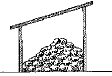
FIGURE 4.1.1-A Work flow for dry
process clay making (A)
A) Dry clay storage. Store enough dry clay to last throughout the rainy season.
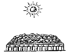
FIGURE 4.1.1-A Work flow for dry
process clay making (B)
B) Drying in the sun directly on the ground, or, better still, on raised brick platforms which can be covered by plastic in case of rain.
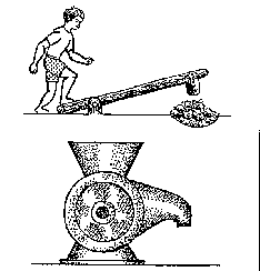
FIGURE 4.1.1-A Work flow for
dry process clay making (C)
C) Making clay powder by hand, with a rice huller or a hammer mill.
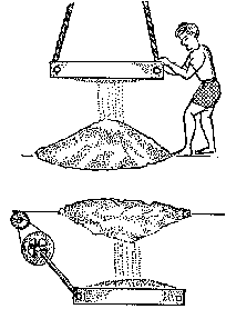
FIGURE 4.1.1-A Work flow for dry
process clay making (D)
D) Screening to remove coarse particles (16-100 mesh depending on required fineness) by hand sieve or motorized vibrating screen.
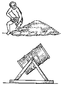
FIGURE 4.1.1-A Work flow for dry
process clay making (E)
E) Mixing with other materials (clays, feldspar, talc, quartz) manually or in a drum mixer.
FIGURE 4.1.1-A Work flow for dry
process clay making (F)
F) Soaking is necessary to allow all clay particles to absorb water ( for a minimum of 24 hours).
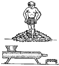
FIGURE 4.1.1-A Work flow for dry
process clay making (G)
G) Kneading can be done manually (or with the feet) or in a pug mill.
FIGURE 4.1.1-A Work flow for dry
process clay making (H; I)
H) Maturing under a plastic cover for a minimum of 3 days, or,
better still , several weeks.
I) The plastic clay will need a little kneading
before being used for forming.
4.1.2.
WET PROCESS
The wet process is used to make finer clay, and is necessary for white bodies where it is necessary to remove iron particles. It is easy and cheap when done by hand for cottage industries, but is complicated and expensive when it is done on an industrial scale.
To do it BY HAND requires only two tanks of brick lined with cement. The work flow is shown in Fig. 4.1.2-B.
Clay preparation BY MACHINE (Fig. 4.1.2-C) follows the same principle as by hand. The machines make the initial costs much higher, but the two methods could be combined. The filter press is the most costly part and it could be replaced by dewatering trays.
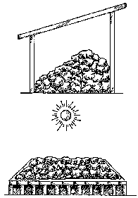
FIGURE 4.1.2-B Work flow of manual
wet clay process.(A; B)
A) Clay storage shed.
B) Clay that is completely dried is
easier to soak , but drying is not necessary.
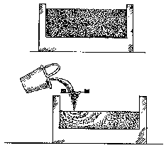
FIGURE 4.1.2-B Work flow of manual
wet clay process.(C; D)
C) Soak clay and water in a tank , until it makes a fluid slip.
NEVER STIR CLAY BEFORE IT IS COMPLETELY SOAKED.
D) The clay slip is screened
and transferred to another tank.
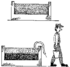
FIGURE 4.1.2-B Work flow of manual
wet clay process.(E; F)
E) The clay is left in the settling tank.
F) When
the clay has settled, clear water is siphoned off and the thick clay slip is
transferred to a dewatering tray.
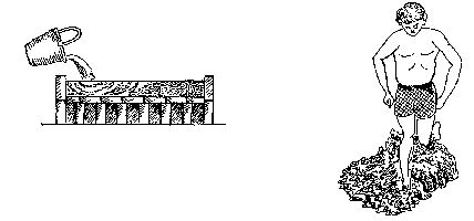
FIGURE 4.1.2-B Work flow of manual
wet clay process.(G; H)
G) Dewatering tanks can be common bricks, or cloth placed in a
depression in the ground.
H) Kneading by hand or foot.
FIGURE 4.1.2-B Work flow of manual
wet clay process.(I)
I) Clay is matured in order to increase its plasticity.
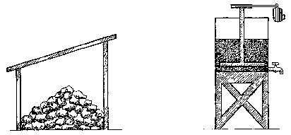
FIGURE 4.1.2-C Work flow of wet
process by machine.(A; B)
A) Clay storage open or covered.
B) Electric-powered blunger
turns the clay into slip.
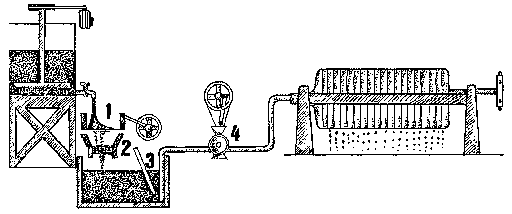
FIGURE 4.1.2-C Work flow of wet
process by machine.(C1;2;3)
C1) From the blunger the slip runs through a vibrating sieve (1)
and a strong magnet (2) which
removes iron particles.
2)From an
underground tank with a stirrer (3) the clay slip pumped (4) under high pressure
into a filter press.
3) In the filter press water runs off and the clay is
retained by filter cloth
FIGURE 4.1.2-C Work flow of wet
process by machine.(D; E)
D) The filter press clay “cakes” are removed from the
press and taken to the pugmill.
E) Pugging is often done in a de-airing pug
mill.
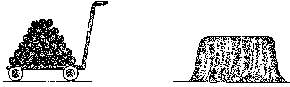
FIGURE 4.1.2-C Work flow of wet
process by machine.(F; G)
F) Pugged clay is transferred to clay storage.
G) Clay is
stored under moist
conditions.
4.2.1. TOOLS FOR HAND-FORMING
4.2.2. THE BASICS: HOW TO MAKE
COILS AND SLABS
4.2.3. ASSEMBLING COILS AND SLABS
4.2.4. USEFUL HINTS
Hand-forming methods use only the hands and a few simple tools. They are the oldest methods of making ceramics, but still are useful in modern times. They require a very small investment.
Typical products made by hand-forming are:
- Small items, such as animal figurines and small sculpture- Large items, such as storage jars for grain and water, special flowerpots, basins for washing clothes, and big sculpture.
The basic operations in hand-forming are cutting, scraping, joining, smoothing and slab making. Tools are easy to make by yourself. Useful tools are:
- for smoothing and cutting: carved wooden tools;- for cutting, smoothing, scraping: metal tools, which can be made from old hacksaw blades and heavy wire. Various shapes made from old plastic buckets, etc.
- for shaping: wooden paddles for beating clay and flattening slabs;
- for joining, finishing: sponges for wetting clay.
Coils are long cylinders or “snakes” of plastic clay. Depending on how they are to be used they can be as small as a matchstick or as large as a man’s arm. There are three techniques which need to be mastered:
Coilmaking
Coils are easily made by rolling plastic clay on a smooth surface. The difficult part is keeping the coil even in diameter and round. This requires some practice. It is helpful to remember to roll the coil from the center to the outside, and to roll it as far as possible each time (from the tips of the fingers to the base of the hand) - this will help to keep it round.
A method requiring more expertise is to start with an elongated ball of clay between the hands, and by rolling the hands back and forth, to gradually cause a coil to move downwards. This is a very useful method when working on large pots, and, when mastered, is very fast.
Coils can also be made by using a hand extruder (see page 78).
Slabmaking
There are several ways of making slabs, all of which require a flat surface to work on:
Small slabs can be made by simply pounding a piece of clay with the hand and a wooden paddle. Or, when the slab is partly flattened, it can be rolled with a wooden cylinder (such as is used for rolling pastry dough).
Large slabs can be started by slamming a ball of clay down on the floor, turning it over, and repeating the process until it is sufficiently thin. With practice, slabs almost I meter by I meter can be made quickly with this method.
Large, thick slabs for big flowerpots, etc., are best made on a flat floor - it is helpful to sprinkle dry clay powder to keep the slab from sticking. Partly-flattened lumps of clay are joined by walking and jumping on them. They then are thinned as much as required by further jumping and beating with a wooden paddle.
Another way to make slabs is the “cutting method”. This is often used for making rough slabs for tiles. A large rectangular lump of clay is prepared and set on a flat surface. Then a series of long wooden sticks, cut the thickness of the desired slab, is piled up on either side of the clay. These are used as guides for a cutting wire. After each slab is cut, one stick is removed from each pile, and the next slab is cut. This is a cheap and fast method.
Slabs are sometimes made by pouring deflocculated slip. This process is described in the section on slip casting.
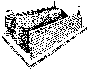
FIGURE 4.2.2-B Cutting slabs with
wooden stick guides.
4.2.3.
ASSEMBLING COILS AND SLABS
No matter how you make slabs, they are used as basic building elements for a large variety of shapes. Because slabs are most appropriate for flat surfaces, they are most frequently used for the bottoms of large pots, and for constructing rectangular shapes.
rectangular forms
Rectangular shapes are made by first letting the slabs dry to the leather-hard (half-dry) stage. Pieces of the appropriate size are cut and assembled.
joining parts
Joining leather-hard slabs must be done carefully, so that the joints do not separate while drying. The safest method is shown in Fig. 4.2.3-B.
coils
Forming pots by coil is a standard method, which is still used in many countries for making traditional pottery as well as more modern items. Usually the coil method is combined with beating and scraping, and is often used in combination with the potter’s wheel (see below).
The coil method is best used for large round or curved shapes, such as flowerpots, that are too big to make on the potter’s wheel.
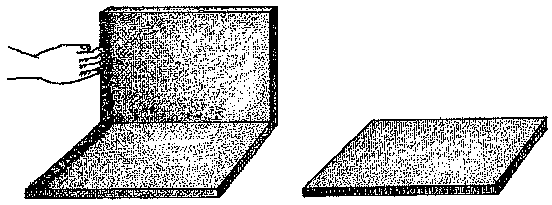
FIGURE 4.2.3-B Slab joining step by
step.(A)
A) Apply a coat of slip to the surfaces to be joined.
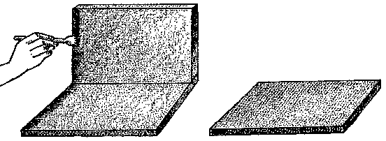
FIGURE 4.1.2-C Work flow of wet
process by machine.(B)
B) The slip then is worked into the clay by scratching
the surface - this is most easily done with a tool such as an ordinary fork, or
a piece of sheet metal with a serrated edge.
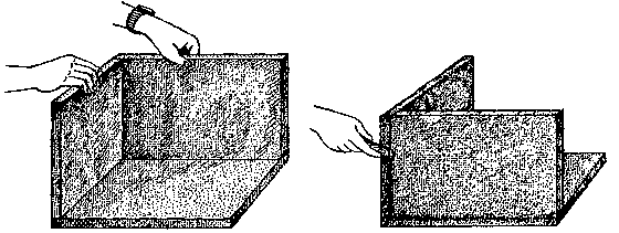
FIGURE 4.1.2-C Work flow of wet
process by machine.(C; D)
C) The pieces are then pressed together while the
slip is still wet. REMEMBER TO FIRST APPLY THE SLIP , THEN TO SCRATCH IT -this
works much clay particles to join very securely. When the better than doing it
the other way around.
D) After joining the pieces, gently beat all the seams
with a wooden paddle. This helps the seams with a wooden paddle.This helps the
joining slip is no longer wet, the seams can be finished with wooden and metal
tools.
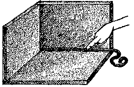
FIGURE 4.1.2-C Work flow of wet
process by machine.(E)
E) Joins of large pieces can be reinforced with a clay
coil on the inside.
The basic method is:
- Make a base for the pot from a slab. This usually is placed on a wooden plank or a plaster plate (bat), and it is easiest to put this on top of a turntable of some kind (although not essential).
- A supply of coils is then made and kept near the working area to be used immediately (coils should not be stored, as they are likely to dry out). Otherwise, many potters make coils as they go along. The diameter of the coils depends on the size of the pot, but usually will be between 2 and 5 cm.
- Join the first coil to the bottom slab very carefully - this is best done with clay slip and scratching as for slab pots (see above). For large forms, the coil is pinched between the fingers to make it slightly thinner and to raise it up.
- Then build up the walls of the pot by adding a coil all around. It works best to add the coil to the inside of the wall, and then to pinch the two coils together. This makes a strong joint, since it is overlapped, and, because the wall tends to move out when pinching it, it makes it easier to control the shape.
- Repeat the process until the pot is tall enough. Large pots can be built up over a period of several days to allow the clay walls to harden in order to carry the additional weight.
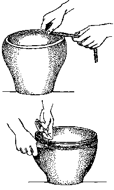
FIGURE 4.2.3-C A coil is added all
around whike one hand pinches the inside. Once the coil is on, pinching and
smoothing are done on the outside.
remember
Usually coil pots are made narrower and thicker than their final
shape. As they start to dry, the final shape is given by beating the walls of
the pot, which makes the clay thinner and expands the form. This is done by
holding a rounded piece of fired clay inside and beating the pot with a flat
wooden pallet from the outside (Fig 4.2.3-C). The surface is then smoothed by
sponging and scraping.
It is difficult to make coil pots round and
symmetrical - this comes with practice, and an expertly-made coil pot is
difficult to distinguish from a wheel-thrown pot.
4.2.4. USEFUL HINTS
- Clay for coiling and slab making should be less plastic than clay for throwing.
- If coils are added too rapidly the lower part may sag. When making large pots, allow the walls to dry while keeping the rim moist.
- When joining different parts make sure they have the same moisture content otherwise the pot may crack when drying.
- Allow large pieces to dry slowly by covering them with plastic. Parts of the pot tending to dry faster, like handles, can be covered with wet cloth or plastic so they will dry at the same rate as the rest of the pot.
4.3.1. CLAY REQUIREMENTS FOR THE POTTER’S WHEEL
4.3.2.
TYPES OF POTTER’S WHEELS
4.3.3. FORMING ON THE POTTER’S WHEEL
4.3.4. TOOLS FOR THE POTTER’S WHEEL
4.3.5. FINISHING ON THE
POTTER’S WHEEL
4.3.6. DRYING
The potter’s wheel was invented in order to make pots faster than is possible by hand methods. It is a very old tool, and has many variations from country to country. All potter’s wheels work on the same principle, which is that a rotating plate (wheelhead) spins a lump of clay around, which then can be pushed and shaped by the hands of the potter. There are many local variations in size, method of propulsion, height, etc.
Shapes that can be made on the wheel are necessarily round, but they may be altered after forming by beating or stretching to make oval or square shapes.
The process of forming clay on the wheel is called
“throwing” in English. Nobody knows why this word is used - its
meaning has nothing to do with “throwing” a rock. Usually the forming
process is referred to as “throwing a pot” or “turning a
pot”, and the skilled worker who does so is called a “thrower” or
“turner”.
4.3.1.
CLAY REQUIREMENTS FOR THE POTTER’S WHEEL
Almost any kind of plastic clay can be used on the wheel, and sometimes clay is used that is very difficult to shape (such as porcelain). Ideally, though, most potters prefer clay that is quite plastic, free from rocks and roots, and strong enough to hold any shape. These requirements are met by clay that has been carefully prepared, and then matured for several weeks or months (even years in some cases) to develop plasticity.
clay for small and big pots
For small pots, the clay can be fairly soft, but not so soft
that it loses its shape when removed from the wheel. Potters who make large
items often prefer clay that has up to 30 % grog or sand to reduce shrinkage,
and prepared as stiff as possible in order to prevent it from collapsing. Grog
can be very fine (even dust) if smooth finishing is necessary, but often is up
to 20 mesh in size. It is always best to have a variety of grog sizes for
example from 60 to 30 mesh.
4.3.2. TYPES OF POTTER’S
WHEELS
There are many types of potter’s wheels, and generally they are chosen to suit work habits of the particular culture. There are two main categories: unmotorized and motorized. All potter’s wheels have the following main parts:
Flywheel: a heavy circular disc that provides momentum. It sometimes is also used as the working surface. Flywheels can be made from wood, cement, steel, clay/cow manure, car tires or combinations of these.
Wheelhead: a circular disc that is used as the working surface to which the clay is attached. Wheelheads are made from steel, aluminum, wood, plaster of parts, cement, etc.
Axle: the shaft to which the flywheel and wheelhead are attached. Axles are usually made of wood or steel.
Bearing(s): the device in which the axle rotates. Bearings may be metal bushing types, ball bearings, wood, leather, or stone.
Power source: this is either the foot, the hand or a motor.
UNMOTORIZED WHEELS
Unmotorized wheels usually depend on a heavy flywheel to keep them moving once started. The main types are:
Lightweight “turntables”: These are used for making small pots, and are nothing more than a round wooden plate about 20 cm in diameter fastened at the center to a round stick that turns in a hole in the ground. The potter attaches a small lump of clay, which is shaped with one hand while he rotates the wheel with the other hand. Often, the “coil and throw” method is used (see below).
Advantages: very cheap; often one potter will have a dozen or more wheels which he works on in rotation.
Disadvantages: is only suitable for fairly small products.
Asian low wheel (single bearing): This type of wheel has a combined flywheel and wheelhead, which may be from 60 cm to 100 cm in diameter. It can weigh up to 50 kg. The axle is usually wooden and very short, and has a pointed end which rotates in a single stone bearing. Sometimes the axle is fixed to the flywheel and the bearing is set into the ground, and sometimes it is done the opposite way. The wheel is usually rotated with a stick that is placed into a socket on the edge of the wheel. After it is started, the weight of the wheel keeps it going level, based on the gyroscopic principle (like a toy top). It is suitable for small products such as simple cups which are made very quickly entirely by throwing; larger products are partly thrown on the wheel and finished by beating and stretching.
These wheels are traditionally made from wood, or from a wood and bamboo frame which is covered with a heavy layer of clay mixed with straw, cow’s dung, hair and sugar.
Nowadays, the wheel is often made from a cast cement disc, or from a truck tire, mounted on a wooden crosspiece which is attached to the bearing.
Advantages: easy to make with low technology and local materials.
Disadvantages: Because of only the one bearing, the wheel does not stay level. This makes finishing on the wheel very difficult. Large pots cannot be made by throwing alone.
Asian low wheel (two-bearing type): This wheel also sits near the ground, and also uses its flywheel as the wheelhead. It has a slightly longer axle set in the ground, and the flywheel is fitted with two bearings (which may be wooden, or preferably ball bearings). As above, the wheel is rotated with a stick.
Advantages: Because the wheel is stable, it permits throwing larger forms quite thin, and accurate finishing of the bottom is possible. Because the potter works in a squatting position, there is no strain on his back (this is also true for the single-bearing type above).
Disadvantages: The large diameter fly wheel keeps the potter from getting close to his work. This is not really a problem for a skilled potter.
European kick wheel: This type of wheel has a long axle, and a separate flywheel and wheelhead. The flywheel may weigh from 30 to 150 kg. The potter works in a sitting position, and can rotate the wheel with his feet while working on the clay, which makes the speed easy to vary as required.
Kick wheels may be constructed with wooden or metal frames, and the flywheel may be made of wood, cement, or steel. The main requirement is an extremely sturdy frame that will not vibrate when the flywheel is kicked.
Advantages: The potter can get closer to his work because of the small wheelhead, which makes it easy to brace the arms for stability. It is also a convenient wheel for finishing,
Disadvantages: Puts strain and stress on the potters back because of the awkward sitting position, makes it difficult to see the shape of the pot because the eyes are above it, causes uneven strain on the leg muscles because one leg works harder than the other. It is a very heavy machine and is difficult to move to another location.
Treadle wheel: This is in principle like a kick wheel, but the axle has an eccentric which is driven by an attached foot treadle, and the flywheel is much lighter in weight (10-20 kg). The potter can work either standing or sitting, and unlike with other wheels keeps his foot working the treadle continuously.
Advantages: The body is not excessively strained because of the standing position, and the wheel speed can be easily varied with the foot treadle.
Disadvantages: mechanically more complicated than the above wheels, but not difficult to construct with simple machine shop facilities.
Two-person wheels: These wheels use one person to turn the wheel, while the potter works the clay. This can be done with the Asian two-bearing wheel, where one person rotates the wheel with his foot; or sometimes a special wheel with a flywheel and separate wheelhead is equipped with a hand-driven crank which drives a cycle chain and gear attached to the axle. A third version is shown in Fig. 4.3.2-F
Advantages: This system is often used for making very large pots by the coil and throw system, when a single thrower cannot manage to turn the wheel and throw at the same time. It also is used where labor is very cheap: otherwise it is a very costly method.
Disadvantages: Requires too much manpower; if electricity is available, it is usually cheaper in the long run to invest in a motorized wheel.
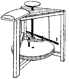
FIGURE 4.3.2-E The treadle wheel is
operated by pushing the foot treadle (1) back and forth.The foot treadle can be
placed either on the left or the right.
MOTORIZED WHEELS
There are many variations on motorized wheels. The two main types use fixed speed motors or variable speed motors.
fixed speed motors
These wheels all use standard AC electric motors. Usually, the smallest size motor for continuous production is 0.5 HP. If large pots are being made (up to 25 kg), it is better to increase to 1.0 HP or for very large pots (25 kg and more) 2.0 HP.
Sometimes motors are directly coupled to the wheel, which allows only one speed to be used. This means the wheel is either running full speed or stationary. (IMPOR-TANT: do NOT try to make an AC motor work with a variable resistor (rheostat) - this will burn up your motor at low speeds). Fixed speed wheels are suitable for producing the same product repeatedly (for example, factories making only large flowerpots sometimes use this system). In fact, some factories have one large motor connected to several potter’s wheels with a shaft and belt system.
The advantages of a one-speed wheel are the low cost and mechanical simplicity. The disadvantage is lack of versatility.
changing the speed
Potter’s wheels that have to produce a variety of sizes use several different systems to convert fixed speed motors into variable speeds:
Friction drive: This simplest system is also called the “power-assisted kick wheel”. It is simply a kick wheel which has a motor added. The motor is provided with a rubber wheel on its shaft, and is mounted in such a way that the wheel can be pressed against the flywheel by use of a pedal. Essentially, this replaces kicking with the foot, which can be done if there is a power failure. The speed of the wheel is controlled by engaging and disengaging the motor. This is a simple system to install, and is very reliable - it only requires periodic replacing of the rubber drive wheel.
A variation of this wheel was developed in Nepal. It has the advantage of low cost and light weight, because the flywheel and wheelhead are combined. The maximum speed of the wheel is about 200 r.p.m., which has proven to be suitable for all sizes of product.
Cone drive: Another old system that is often used in factories is the “cone drive” system. Between the motor and wheelhead is a pair of cones that rotate against each other, and move up and down to vary the speed. This is a fairly complicated system to manufacture, as well as being expensive, and has mainly been replaced by electronically-controlled DC motors.
Ring cone system: A variation on the cone drive system is called the “ring cone” system - the motor has a metal cone mounted on its shaft, and the whole motor can be moved in and out, so that the cone drives a rubber ring connected to the wheelhead at variable speeds. This type of wheel usually is made to run from almost 0 r.p.m. up to a maximum of 300 r.p.m.
If you have to construct your own wheel (with the help of a simple machine shop), it is probably best to use the friction drive system, as this can be managed by a mechanic who is unfamiliar with potter’s wheels.
variable Speed Motors
There are two types of variable speed motors. The older type uses the principle of movable brushes to provide variable speed with constant torque. These motors are expensive, and are difficult to find nowadays. They have been replaced by variable speed electronically-controlled DC motors, which are also quite expensive.
DC motor wheels
The advantage of a DC motor is that it provides variable speed
with constant torque, and can be controlled very accurately. The potter’s
wheel is mechanically simple, because the motor is coupled with a V-belt to the
wheelhead. Unless you have a lot of money to spend, this type of wheel is not
recommended, especially in rural areas where repairs are a problem. There is no
doubt that this is the system for the future, however.
4.3.3. FORMING ON THE
POTTER’S WHEEL
It is not the intention of this book to give detailed instructions for using the poker’s wheel. There are many books which describe the basic technique, and it is something that can only be learned with the help of an experienced teacher. It should be remembered that throwing is a highly-skilled technique, and usually requires years of practice before the potter deserves to be called a “master potter”.
There are a few advanced techniques, however, which are not often described in books, and which can be easily understood and learned by an experienced thrower: some of these are described below.
OPEN FORMS
Open forms are those where the mouth diameter is larger than any other diameter of the pot. This includes cups, bowls, flowerpots, plates, etc.
Here is a list of suggestions for successful shaping:
general shaping techniques
When producing a large number of identical shapes, weigh the clay lumps before starting to work. A measuring tool is set according to the size of mouth and depth of the pot. Keep a record of the weight and measurements and a drawing of all your standard products.
Open forms are likely to warp in drying and fir-ing: a rim that is a little bit thicker than the wall of the pot, and which is given a convex curve, will help to hold the shape of the pot. The rim should be rounded (without sharp corners) to prevent chipping in use.
Never use clear water for throwing. It will “cut” the clay and cause the pot to collapse more easily during throwing. Instead use a fairly thick clay slip for throwing.
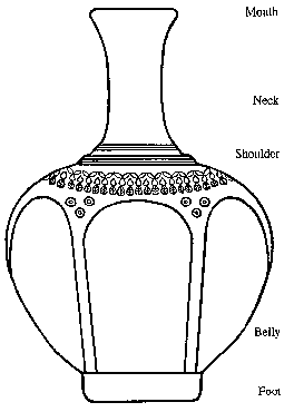
FIGURE 4.3.3-A The various parts of a
pot are named after the human body, as shown in the drawing. From the bottom up,
they are 1) the foot ( if it is a ring, called foot rimg), 2) the belly, 3) the
shoulder, 4) the neck, 5) the mouth (or rim).
FIGURE 4.3.3-B A post gauge placed
next to the wheelhead is used when throwing many pots of the same size.The upper
pointer measures the height and width and a second pointer may be used for
marking the width of the belly.
big bowls
Bowls of 10-25 kg require a special technique, and to be made in one piece a motorized wheel is best. The clay should be as stiff as possible and addition of grog helps.
A wooden or plaster bat should be fixed to the wheelhead first, so that the pot can be removed when it is finished without collapsing it. If you forget to do this, it is helpful to fasten a piece of newspaper over the mouth of the bowl, using a little water to stick it on. There are a variety of “lifters” which help to remove large pots from the wheel: a large flat wooden scraper can be pushed under the pot, or two flat pieces of sheet metal can be used.
CLOSED FORMS
Closed forms are those where the mouth diameter is smaller than the largest diameter of the pot: this includes bottles, vases, etc.
big bottles and jars
Big jars for storage, lamp bases, etc., of 10 to 25 kg can be thrown very thin in one piece if the clay is stiff enough and a motorized wheel is used. It requires a special technique in order to get enough height and to keep the mouth small. For best results, a plaster or wooden bat should be fastened to the wheelhead, so the finished pot can be removed without collapsing.
- If the clay is the correct stiffness, and the throwing is well done, the result will be a jar with a wall about 0.5 cm thick above the belly, and about 1 cm thick below the belly. The only thick area will be the bottom 5 or 10 cm, which requires some trimming.- Another way to make big jars is by joining 2 or more sections, or using a combination of coiling, throwing and beating. Fig. 4.3.3-E shows how potters in Swebo, Burma, are doing this.
JOINED FORMS
Joined forms are assembled from separately-thrown sections: they include large bottles, cups with stands, candlestands, and other forms that cannot be made in one piece. They also include forms with lids - although these are not physically joined, they need to be made to the same degree of accuracy. All joined forms require careful measuring. It is also important to make all the pieces at the same time, so that they shrink at the same rate and will fit correctly. IT NEVER WORKS TO MAKE LIDS AFTER THEIR POTS ARE ALREADY DRY!
lids
The main purpose of a lid is either to keep things from getting into a pot, or to keep the contents of the pot from getting out. For this reason, lids should fit accurately.
interlocking systems
There are many different kinds of lids, which differ mainly in the way they fit together. This is called the interlocking system. Lids may fit inside the mouth, outside the mouth, etc. Measuring tools should always be used for fitting lids correctly. A skilled potter can make lids that fit tightly without much trimming, but usually it is best to make the lid slightly oversize and then fit it accurately when trimming. Also, if you plan to glaze both the mouth of the pot and the lid, there needs to be enough space for the thickness of the glaze.
knobs
The knob is a small round handle attached to the lid, used for lifting it off the pot. Knobs may be small and solid, or are made hollow for larger sizes. Instead of a knob a pulled handle can be placed on top of the lid.
lids that are thrown right side up
Some lids are thrown in the same position as they will sit on the pot. Often, the knob is made at the same time. This type of lid only needs a small amount of trimming.
lids that are thrown upside down
These lids are thrown like bowls. The rim becomes the part that interlocks with the mouth of the pot. This type requires more trimming to finish the knob. There are many ways to make the knob: A) it can be separately thrown and attached after trimming, B) a small piece of plastic clay is centered on the trimmed lid and shaped into the knob, C) the knob is thrown as the base of the lid (Fig. 4.3.3-G (1) & (2)) and trimmed to shape, D) a handle is pulled and attached to the top of the lid (Fig. 4.3.3-G (3)).
lid and pot thrown in one piece
Skilled throwers can throw small containers with lids in one piece. The lid is made as a continuation of the container as shown in Fig. 4.3.3-H (1). The thrown piece is left until leather-hard and then cut and trimmed.
cups with stands (goblets)
Although these are often attempted in one piece, they never are really satisfactory because it is difficult to remove clay from the stand when finishing. They are best thrown (at the same time) as a cup, and a stand which is made upside down. When both are leather-hard, it is easy to center the cup upside down on the wheel, join the stand, and then remove excess clay while making a smooth connection.
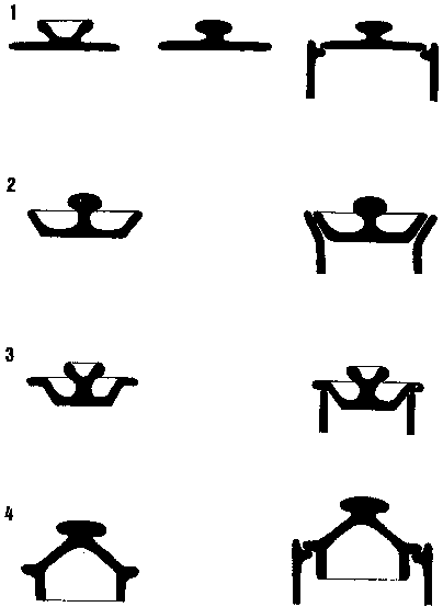
FIGURE 4.3.3-F Lids that are thrown
right side up. Their interlocking with the pot is shown in the right column.
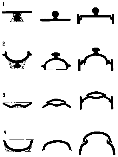
FIGURE 4.3.3-G Lids that are thrown
upside down. The left column shows how the lids are thrown on the wheel. In the
middle is shown how they are trimmed and right column shows the interlocking
with the pots.
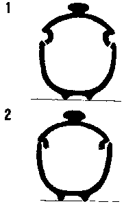
FIGURE 4.3.3-H Lid and pot thrown in
one piece (1). When leather-hard, the lid and pot are separated and trimmed to
fit.
two-piece bottles
Unless you are a highly-skilled thrower, it is difficult to make
large bottles with small, tall necks in one piece. It is much easier to throw
the body and close it in to the base of the neck, and then separately throw the
neck. When the parts have stiffened enough to be picked up without deforming,
they are joined - this is best done by finishing the foot of the bottle,
centering it on the wheel, and then joining the neck while the wheel is
rotating.
4.3.4. TOOLS FOR
THE POTTER’S WHEEL
The tools that you use for the potter’s wheel are mainly a matter of personal preference. The main categories of tools are:
wetting and smoothing: sponges of various sorts (the best are natural sea sponges), a piece of cloth, a piece of soft leather.
cutting: A needle tool is essential for cutting rims and checking wall thickness. This can be made from a big needle, a nail, a piece of wire. A knife can be used, or a sharpened piece of wood or bamboo.
shaping: For smooth surfaces, wooden, plastic, rubber or metal “ribs” are used, mainly on the outside but sometimes on the inside of the pot.
finishing: A triangular piece of sheet metal or a sharp wooden knife is useful for undercutting the bottom before removing the pot from the wheel.
measuring: A variety of wooden sticks, calipers, etc., are used for accurate measuring of mouth size, lid size, depth of pot, etc.
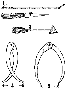
FIGURE 4.3.4-A Tools for throwing:
ruler (1),pointed knife (2), V-shaped cutter for the base (3), calipers for
measuring both inside (4) and outside (5).
4.3.5. FINISHING ON THE
POTTER’S WHEEL
Finishing requires just as much skill as throwing, and profitable production depends on efficient finishing. By “finishing”, we mean the process of removing excess clay from the bottom of the pot, and forming the foot ring that the pot sits on. This is sometimes called “trimming”. The amount of finishing and the style of finishing depend upon the quality of the product being made. Common pottery normally is not finished very much, if at all, but high quality pottery also needs high quality finishing.
Different qualities of finishing are described below, starting with the simplest (for common pottery) and going on to the most complicated. Quality finishing takes a lot of time and is too costly for common pottery often, making a foot ring takes longer than the making of the pot itself.
common pots
Cheap storage jars and other low-cost items are simply cut off the wheel and dried. With some clays, this results in cracks in the base, which are caused by not compressing the bottom of the pot enough when opening up the clay. This happens frequently when making multiple small pots from a single large lump of clay. If this is a problem, it usually can be corrected while throwing in the opening-up stage: the bottom is opened out as usual, then the fingers move from the outside in to the center of the bottom, while pressing downward. This compresses the clay particles in the bottom.
Another way to correct the problem is to beat the bottom of the pot when it is leather-hard (half dry). This is done by placing the pot on a plaster of parts bat, and using a round wooden stick with a flat end to compress the bottom from the inside.
rolled foot
The foot of a pot can be rounded and finished when leather-hard by rolling it on a flat surface. It is also a good idea to slightly press in the bottom to make it sit better and to help prevent drying cracks.
better quality pots
These require foot rings. The purpose of the foot ring is to give the pot a stable base to sit on, and especially to make setting in the kiln easier. The foot ring is usually not glazed(except for high biscuit, low glaze firing tableware), and it makes a logical stopping place for the glaze.
The process of making the foot ring involves removal of excess clay. This is called “trimming” or “turning” (the same word is used for lathe work. This is confusing, because the same word is sometimes used for throwing!). Trimming needs to be done when the clay is at just the right stage of leather-hardness - otherwise it is difficult and the result will not be satisfactory. There are many different tools used, and choosing a tool is mostly a matter of individual preference. The main types of tools are wooden tools, metal tools, and wire loop tools - a variety is shown here.
centering for trimming
The first step is to center the pot UPSIDE DOWN on the wheelhead. This requires a lot of practice before it can be done quickly and easily.
- One method is to slowly rotate the pot, and hold a pointed tool steadily near the foot: it will make a line where the pot is farthest from center - this line is pushed toward the center of the wheel, and the process is repeated until the tool makes an even line all around the foot. This is a slow process, and normally is done only for special shapes, or pots with fairly small mouths that do not sit stably on the wheelhead. The pot is then secured to the wheelhead with pieces of plastic clay.
- For small and medium open forms, experienced throwers use the “tap cantering” method. A small amount of water is first placed on the wheelhead in the area of the pot’s mouth. The pot is then placed upside down as much on center as possible, and the wheel is rotated at medium speed. While slightly pressing the bottom of the pot with one hand, the potter gently taps the pot with his other hand until it is on center (this process is impossible to describe in writing, and must be learned from an experienced potter). It needs to be done quickly and surely, and if the pot is at the right of stage of dryness, the water will stick it securely to the wheelhead.
chucks
When trimming a large number of identical shapes, or shapes that will not sit on the wheelhead (closed forms), the potter makes use of a “chuck”. This is a cylinder of bisque-fired or dry clay, or sometimes plaster of parts, which is used to hold closed forms inside it, or open forms outside it. The potter makes his own chucks according to his products.
When using chucks, the main problem is to hold the pot firmly without damaging it. The chuck needs to be centered on the wheel, and then a coil of plastic clay is fastened inside it, and also must be centered accurately. A plastic clay chuck, on the other hand, is sometimes covered with a piece of cloth or plastic to keep it from sticking to the pot.
In either case, the pot is placed on the chuck, and then is centered by making sure its bottom is perfectly level. If done correctly, the entire pot will then be on center, and can now be trimmed.
Trimming itself is done in many different ways, all of which work satisfactorily if the potter is skilled. Usually, the foot ring is located first, and then excess clay is removed from the inside. A skilled potter knows when the bottom is thin enough just by the feel of his tool. If he is in doubt, he can tap gently on the center of the bottom with a finger, and the sound will tell him if the thickness is correct. Then the excess clay is removed from the outside of the foot ring, and the ring is smoothed with a fingertip or a damp sponge.
It is usually helpful to use a smooth wooden tool to compress
the bottom, working from the outside to the center. With sensitive clay, this
also helps to prevent cracks in the base.
Before removing the trimmed pot
from the wheel, it should be smoothed with a damp sponge (although many potters
like to leave the marks of the trimming tool).
After the completed pot is removed from the wheelhead, the rim should be smoothed with a sponge, and is usually placed upside down for drying.
If very high foot rings are required, they are either made separately as for goblets (above), or another technique is to throw the foot ring directly on the pot. After centering the leather-hard pot upside down on the wheelhead, either a ball of plastic clay is joined to the bottom and thrown to the necessary shape; or, for larger pots, a thick ring may be thrown separately, joined to the bottom, and then thrown to the final shape.
The foot ring should in any case be made wide enough to give stability to the pot. A bowl with a narrow foot ring easily tilts, spilling its contents.
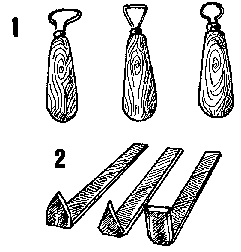
FIGURE 4.3.5-A Trimming tools: wire
loop tools (1) and tools (2) made from metal strips.
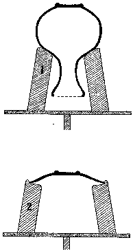
FIGURE 4.3.5.-B Chuck used for
trimming a vase with a narrow mouth (1).Another chuck (2) is used for trimming
saucers of identical shape.
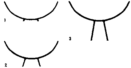
FIGURE 4.3.5-D A bowl’s function
and appearance depend on its foot.Here three different types are shown .(1) is
made by turning away excess clay , (2) is made by throwing on the pot and (3) is
made by joining individually-made leather-hard parts; bowl and foot ring.
4.3.6. DRYING
The main problems occurring during drying are warping and cracking. As with all clay products, the best way to prevent these problems is by drying slowly and evenly. This means avoiding wind direct sun, and covering products in dry weather.
helpful hints for drying
Open forms (cups, bowls, plates) of the same size are best dried stacked rim to rim. This helps to prevent warping.
- When drying pots to the leather-hard stage for trimming, they need to be watched very carefully to be sure that the rims do not get too dry. When the rims are leather-hard, it is a good idea to turn the pots upside down until the foot is ready for trimming.
- Large open pieces can have their mouths covered with plastic to keep them from drying too fast.
- Covering pots with wet cloth and plastic can keep them from drying indefinitely.
Pots that have accidentally become too dry for joining should usually be thrown in the scrap bucket. However, they can sometimes be wetted by dipping them in clean water.
4.4.1. HANDLES
4.4.2. JOINING COMPLICATED FORMS
4.4.3.
SPECIAL JOINING TECHNIQUES
Many products require joining of several parts. In general, when
clay is joined it often causes problems of cracking or separation during drying.
It needs to be done carefully and skillfully in order to be successful. This
section discusses special problems in joining.
4.4.1. HANDLES
Handles are formed in a variety of ways. The small workshop usually makes handles by hand or extrusion, and then joins them to leather-hard (and already-trimmed) products:
coil
A coil is rolled to the desired diameter, and then it is shaped by pressing and smoothing with a damp sponge.
pulling
A piece of plastic clay is slightly elongated and then is stretched into a handle by repeatedly pulling it with a wet hand (like milking a cow). The wetting should be done with clay slip, not clean water. Some prefer first to attach a lump of clay to the pot then do the pulling while holding the pot with their other hand. The handle can also be pulled first and then joined.
extruding
Handles are extruded from a hand extruder (see below). This is a fast method for making large numbers of handles. Fig. 4.4.1-B shows a method for unskilled workers to produce quality handles. A skilled potter will not need templates to produce evensized handles.
pressing
Handles are pressed from plastic clay, using a small plaster two-piece mould.
slip casting
This is a standard method for industries producing large volumes of crockery by casting or jiggering. The handles are cast in moulds that produce many handles with one pouring.
drying items with handles
Products to have handles added should be turned upside down as
soon as possible after throwing. This allows them to dry slowly and evenly. Many
products with handles are damaged by cracking that occurs when a wet handle is
joined to a dry product. Dry products can be wetted with clean water before
joining the handle, but this should only be done in emergencies. After joining
the handles, turn the pot upside down for even drying.
4.4.2. JOINING COMPLICATED FORMS
The main point to remember about joining separate parts is that the clay must have reached the correct stage of dryness meaning leather-hard. In general, all parts should be at about the same dryness.
When joining, always:
- FIRST coat both surfaces to be joined with clay slip.
-
Scratch both wetted surfaces with a fork or serrated-edge tool, which works the
slip into the clay.
- Press the two surfaces together firmly.
- If
possible, beat the joined area lightly with a wooden paddle, and work the seam
together with a rounded wooden tool.
Another important point is that drying should be slower than usual, so that the different areas of the pot dry evenly.
Some potters do not need to take this much care when joining
different parts, because they have a tolerant clay body. But if you have
cracking problems you should follow all the steps mentioned above.
4.4.3. SPECIAL JOINING TECHNIQUES
deflocculated slip
If a lot of joining has to be done on a regular basis (for example, a factory that produces rectangular flowerpots using the slab method), it is worthwhile using deflocculated casting slip as “glue”, which is made from the same body as the slabs. This permits faster joining, because the surfaces require a minimum of scratching before joining. It also has about the same water content as plastic clay, so even a thick layer of it will shrink about the same amount in drying, which helps to prevent cracks. (See slip casting and fiberslip below).
pegged joining
When joining big handles or handles that have to carry a heavy load, it is a good idea to use an interlocked joint, similar to a carpenter’s joint. A hole can be cut in the pot, and the end of the handle shaped to fit into it. The surfaces are slipped and scratched a usual (this is a particularly good use for casting slip), then fitted together, and the end of the handle inside the pot is pressed and finished like a metal rivet. This is not usually needed, but if there are problems with specialized products, it does give them an added amount of strength.
4.5.1. APPROPRIATE USE OF THE JIGGER
4.5.2. AVERAGE
PRODUCTION QUANTITIES
4.5.3. JIGGER WORK FLOW
4.5.4. JIGGER MACHINE
PRINCIPLES AND CONSTRUCTION
4.5.5. MOULD MAKING FOR THE JIGGER
4.5.6.
FORMING PROCESS
4.5.7. FINISHING
4.5.8. DRYING
4.5.9. JIGGER
PROBLEMS AND SOLUTIONS
The jigger is nothing more than a potter’s wheel which has been modified to produce uniform products semiautomatically or automatically. It has been a standard forming tool in the ceramics industry for many years, and is likely to be around for a long time in the future, as it continues to develop into a more and more sophisticated (even computer-controlled) machine. Roller head machines are now replacing the jigger machine for flatware production in larger industries.
Basically, the jigger machine consists of a spinning wheelhead which is fitted to hold plaster of parts moulds, and a movable arm which holds a metal profile. Clay is placed in or on the mould, and the operator purls down the profile, which forces the clay into the shape of the product. The forming method is called jiggering .
The forerunner of the jigger is still used in many countries,
usually for making plates with shallow relief designs. Plaster moulds for the
inside curve of the plate are centered and fastened to a potter’s wheel, a
slab of clay is placed on the mould, and the potter smooths and shapes the back
of the plate and foot ring. Excess clay is trimmed from the rim, and the product
is set aside to dry. The rim is finished when it is stiff enough to hold its
shape.
4.5.1. APPROPRIATE
USE OF THE JIGGER
It is a necessary tool for industries which produce tableware, such as cups, plates, bowls, and other open shapes. It is mostly used for products that are round and simple in shape, but there even have been jiggers developed for making oval shapes.
It is not suitable for small, one-man industries, as it is only cost-effective if its full capacity for production is used. One jigger can produce several hundred pieces per day, and the factory needs enough kiln capacity to manage these quantities.
Most forms made on the jigger can also be produced by slip
casting, but this is actually slower and requires more finishing time. The
jigger requires a large number of moulds, but because the moulds are relatively
thin, they can be dried and reused faster than slip casting moulds - they also
do not absorb as much water, since plastic clay is used in the process.
4.5.2. AVERAGE PRODUCTION
QUANTITIES
Average production quantities for the basic jigger vary greatly according to the skill and management of workers, as well as being different for large and small products.
However, the following figures can serve as a guide to setting production quotas:
|
Thailand/Burma: |
1200 teacups per day |
|
India: |
2000 mugs per day |
|
Nepal: |
800 cups per day |
|
Europe: |
1600 sugar bowls per day |
| |
2400 saucers per day |
Semiautomatic jiggers in Europe produce from 8 to 14 articles per minute.
Mould life also varies greatly, depending on the quality of the
product, the quality of the plaster of parts, and care taken in handling the
moulds. Average figures are several hundred times for one mould - high quality
products require more frequent mould replacement.
4.5.3. JIGGER WORK FLOW
JIGGER WORK FLOW AND REQUIREMENTS
raw materials
Plastic clay for jigger work can be any standard clay body. However, it is prepared much softer than clay for wheel throwing. This allows it to be easily shaped in the mould. The clay does not need to be as plastic as for throwing, although plastic clay gets a smoother finish.
mould use
The same mould can be used several times per day, depending on how fast it is dried. Most small producers air-dry their moulds, which usually limits use to twice per day, depending on how dry the air is. Producers using an artificial dryer can use moulds up to 4 times in a single shift.
finishing
The method of finishing depends on the properties of the clay body. Normally, the only finishing necessary is smoothing the mouth. In many factories, this is done at the bone-dry stage, using sandpaper. This is not recommended, because the dust is a health hazard for the operator; it should only be done if a good exhaust fan and dust mask are used. Instead, finishing should be done with a wet sponge at the leather-hard stage (Fig. 4.3.5-C).
FIGURE 4.5.3-A Work flow of
jiggering (A;B)
A) Clay, softer than used for hand throwing, is brought to the
jigger. One worker prepares even lumps of clay ready for forming.
B) A
plaster mould is placed in the chuck and forming is done by bringing down the
inside template.
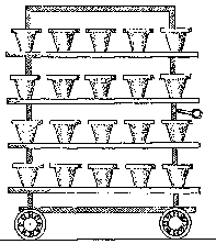
FIGURE 4.5.3-A Work flow of
jiggering (C)
C) The operator takes empty moulds from a trolley rack next to the jigger and returns them when they are filled.When all moulds are finished the rack is replaced with a new one.
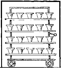
FIGURE 4.5.3-A Work flow of
jiggering (D)
D) The trolley rack with full moulds is placed in a dryer.
FIGURE 4.5.3-A Work flow of
jiggering (E)
E) After the formed items have dried a little they are taken out of the moulds and placed on ware boards. The moulds are returned to the jigger machine.
FIGURE 4.5.3-A Work flow of
jiggering (F; G)
F) Finishing of the rim is done in a spinning chuck.
G) The
leather-hard items are ready for next production step: attaching handles or
drying.
4.5.4. JIGGER
MACHINE PRINCIPLES AND CONSTRUCTION
We describe here only the simplest types of jigger machines, since the more sophisticated ones cannot be made by a simple machine shop. The machine shown from Nepal was constructed using only a machine lathe and an electric arc welder.
main parts of the jigger
Wheelhead: This is equipped with a chuck for holding the plaster mould, as shown. There are two options: 1) chucks made of mild steel or cast iron, 2) a flat wheelhead on which a plaster chuck is fitted. The wheelhead is usually set to rotate at 250-350 r.p.m. Small products like cups can be rotated faster - some machines go up to 400 r.p.m. It is very Important for the chuck to run true.
Because plaster chucks wear out fast, causing the moulds to go off center, they are sometimes reinforced on the inside rim with a rubber lining, a metal ring or a lead collar the latter is melted and poured in place.
Axle and bearings: The axle should be 2.5 cm in diameter, and good quality ball bearings should be used.
Drive system: Machines which have individual motors use pulleys and V-belts to reduce the motor speed and provide mechanical advantage. In factories where several machines are needed for larger production, one large motor often drives a long shaft, and the machines are connected to the shaft with flat belts. In this case, a simple clutch system is necessary for each machine, in order to stop it when necessary.
Clutch: The clutch is optional. Many machines have wheelheads with no clutch. A skilled operator can insert and remove moulds without stopping the wheel. Clutches are of two types: a spring clutch is used with V-belt drives, whereas a sliding belt system is used with flat-belt drives.
Variable speed drive: This is also optional. Most producers make standard products, and one speed is sufficient for products ranging from plates to cups. In more sophisticated machines, a friction drive allows the speed to be reduced for larger items. A cheaper solution is to fit multiple size pulleys on motor and axle so speed can be adjusted by changing the V-belt.
Jigger arm: There are numerous jigger arm shapes. The main requirement is that it be very rigid (it must not vibrate in use), so cast iron is the preferred material. The bearing where it rotates also must be very solid: the usual system is a cone-type bushing, where the cone tension can be adjusted with lock nuts.
Profile or template: Normally, the profile is made from mild steel, which is carefully ground to the exact shape. The steel needs to be at least 3 mm thick. Metal profiles are sometimes backed up with wood to give them better rigidity. The profile will wear down with use, and it is necessary to regrind it from time to time. Additionally, master profiles should be kept for standard production items, so that new working profiles can be made as necessary.
The profile has to be adjusted so it is exactly on center and does not leave a “bump” or spiral in the center of the article.
For limited production items, profiles are sometimes made from acrylic plastic or even from wood. These, of course, have a much shorter working life than mild steel.
The profile is mounted with adjustable nuts and bolts, which allow it to be accurately positioned and shifted as necessary.
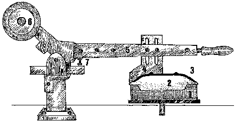
FIGURE 4.5.4-A Jigger system for
forming plates. Main parts are: wheelhead with chuck (1), mould (2), plate(3),
profile (4), jigger arm (5), counter balance (6), stop adjustment(7).
4.5.5. MOULD MAKING FOR THE
JIGGER
As with slip-casting moulds, jigger moulds require a plaster model, master mould, and case mould from which the working moulds are made. (Refer to section 6. on mould making).
limitations on shape
One-piece moulds: Usually, moulds are only made in one piece. Because the product needs to be easily removed from the mould when leather-hard, shapes must be designed for this purpose. Moulds must not have any undercuts which might catch the clay. Also, there should not be any sharp edges - foot rings must be rounded and not very high.
Cylinder shapes are not very successful because the working moulds are very difficult to separate from the case mould. Instead, straight-sided shapes should be slightly tapering.
Two-piece moulds: Sometimes, two-piece moulds are used for shapes that curve in slightly at the top, or have a foot ring that curves out slightly. Usually, it is more efficient to form this kind of shape by slip casting.
decorated moulds: Moulds are often made with shallow relief designs. This is particularly effective with plates. Some factories use this technique, and then finish the plate by hand-carving when leather-hard. This gives an effect that seems 100 % handmade, and greatly increases the retail price of the product.
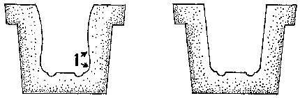
FIGURE 4.5.5-A The left jigger mould
has undercut at (1) This will make it impossible to release the pot from the
mould. The right jigger mould has no undercuts and its slightly tapering shape
makes mould release easy.
4.5.6.
FORMING PROCESS
adjusting profiles:
The profile has to be adjusted so that the jiggered item has the right shape and thickness. This is done by cutting the jiggered item in half with a knife. The thickness should match that of the original sample. The profile may get out of position and its surface will wear out, so the production supervisor should cut control samples at least once a day to make sure products are up to standard.
profile on the inside:
- Prepare balls of clay in advance. They should be weighed for accuracy, but experienced operators will be able to judge the correct quantity by taking lumps from clay on the bench. If clay is prepared in a pug mill the extruded clay wad can be cut in slices of a length corresponding with the required weight. They are then placed in a convenient location for the worker.
- Also prepare ware boards and moulds in advance, which means they MUST BE CLEAN, and set in a convenient location.
- Place a mould in the chuck. (Normally, the machine is running and does not need to be stopped to insert or remove working moulds).
- Place or throw a ball of clay in the mould. It is pressed into the bottom and then opened up with one hand for large items. With small shapes, the profile can be brought directly down on the ball of clay.
- Bring the jigger arm down into the mould, which will force the clay into shape. Excess clay is removed from the top of the mould and from the profile. Before removing the profile, the inside of the article must be wet with water to smooth the surface.
- Remove the mould from the chuck and set it on a ware board.
profile on the outside:
- Prepare slabs of clay in advance. This is usually done by cutting slabs from a block of clay using wooden sticks and a cutting wire (see slabs, above). Slabs can also be beaten out on a wet plaster bat with a wet plaster beater. (If the beater is dry, the slabs will stick - it is soaked in water every night for the next day’s work). Plates made from such slabs need more finishing work. For better quality plates slabs are prepared by throwing on a potter’s wheel or on a bat making jigger machine as in Fig. 4.5.6-B.
- Put a mould in the chuck with the already-prepared slab on it.
- Sponge and press the slab with the hand while it rotates to stick it firmly to the mould.
- Bring the jigger arm down to form the back surface of the plate, at the same time letting water drip from a sponge to smooth the surface.
- Remove excess clay.
- Remove the mould and plate and set the latter on a ware
board.
4.5.7. FINISHING
Finishing is a separate operation and is best done by a separate worker if there is enough production. This keeps forming and finishing going continuously.
Finishing can be done on a jigger wheel, or on a potter’s wheel. The wheel is set up with a chuck, which often is thrown from plastic clay to fit the inside of the form. It is best, however, to make a chuck from plaster which exactly fits the product.
All clay products are best finished when they are leather-hard.
In this case, the piece is set in the chuck, the wheel is rotated, and the
outside is finished with a wet sponge. Normally, the area most needing finishing
is the mouth or rim.
4.5.8. DRYING
Drying of jigger products requires no special techniques, but
the general recommendations for potter’s wheel products should be followed,
such as setting pieces rim to rim to prevent warping. Wet jigger moulds will not
release the jiggered item and in order to increase production artificial drying
of moulds should be considered (see chapter 9.2).
4.5.9. JIGGER PROBLEMS AND
SOLUTIONS
Problem: Clay sticks to the moulds.
Solution: This is sometimes a difficulty with new moulds. They may be dusted with a small amount of talc or fine grog powder to prevent sticking. Usually, the problem stops after a mould has been used a few times.
Problem: Breakage of moulds.
Solution: Early breakage of moulds may be caused by poor quality plaster of parts. Sometimes, adding about 5 % cement to the plaster mix will help the strength, although it is better to look for another plaster supplier, if possible. Or moulds may be too thin, especially in the top rim, and should be made thicker. Moulds are often reinforced by setting a wire ring inside the rim during mould casting.
Problem: “Feathering” in the bottom of the inside (cups, bowls), or on the bottom of saucers - this Looks like a spiral or “butterfly”.
Solution: Correct adjustment of the profile. Metal of profile too thin, which causes “chattering”. Jigger arm too thin, which causes vibration. First make the profile thicker or place a wooden plate on its back. If this is not enough try to reinforce the jigger arm.
Problem: Rapid wearing out of plaster chucks.
Solution: Metal rings can be cut accurately from 2-mm mild steel, and set into the rim of the chuck for long chuck life. A rim of rubber inside the chuck is often used but it is difficult to make it run true. An old method is to pour melted lead into the chuck Am. Melted lead does not harm the plaster and it is easy to trim.
Problem: Uneven thickness of products.
Solution: Wrong setting of the profile causes uneven thickness of a product’s cut-through profile. Profile is refixed or it may need to be reground. A plaster mould running off center causes the jigger item to be thick on one side and thin on the other. The problem may be that the jigger head or plaster chuck is off center or that the clearance between mould and head has become too great. The plaster mould may from the beginning be off center due to faulty original models or case moulds.
4.6.1. HAND EXTRUDERS
4.6.2. MOTORIZED EXTRUDERS
4.6.3.
TYPICAL EXTRUDED PRODUCTS
Extrusion means the process of forcing plastic clay through a
shaped mouth, called an extrusion die or nozzle. The verb is “to
extrude”. The simplest extruders are hand-powered for forming handles,
etc., and the most complicated ones are very sophisticated machines for
producing large products like pipe.
4.6.1. HAND EXTRUDERS
Hand extruders consist of a cylinder to hold clay, and a piston to force it through a die attached to one end. A medical syringe (with the needle removed) can be used to produce very small coils for decoration - so this is actually a very simple extruder. Hand extruders can be used for small solid extrusions (like handles), and can also extrude hollow pipe up to about 15 cm in diameter. There are two systems for providing the necessary pressure:
- Screw system: This uses a long screw attached to the piston to compress the clay. This machine is sometimes called a “wad box”.
- Lever system: A lever arm is attached to the piston, and pulling it down forces the clay through the die. There are two ways to drive the lever arm: by a “ratchet” system, where the end of the lever is engaged in slots on the support arm, or by the faction system, where a metal ring holds the lever arm in position. In either case, the principle is the same as a “bumper jack” for automobiles, and this type of jack can actually be modified to power an extruder.
Dies for the extruder can be made from mild steel, acrylic plastic, or waterproof plywood. The extruder cylinder is fitted with a screw on cap which holds the dies, so it is easy to change them as required.
Clay for hand extruders needs to be fairly soft, so that it can
be pushed through the die easily. If pipes are being extruded, they can only be
made relatively short, because the soft clay is difficult to transport without
collapsing. These “pipes” are normally used as cylinders for making
products like flowerpots.
4.6.2.
MOTORIZED EXTRUDERS
Motorized extruders are simply pug mills equipped with extruder
dies according to their purpose. Most pug mills are used for the purpose of
producing plastic clay body for other forming methods, but almost any pug mill
can be used for extruding products such as small hollow bricks.
Specially-designed pug mills are used for extruding stoneware pipes and split
tiles, which require higher pressure and more control.
There are several
different kinds of pug mills that can be made with simple technology. The main
parts are:
- Motor: ranging from 1 HP for very small mills up to 30 HP and more for the largest ones.
- Reduction gear system: Because speeds range from 15 to 25 r.p.m., reduction is usually done with gears. This may be a combined V-belt, pulley and gear system, or direct gear system. Frequently, either an automobile transmission or differential gearbox is used.
- Axle and blades: The main problem with the axle design is that any gears or bearings should be isolated from the clay. Blades can be made simply from flat mild steel. When thorough mixing is required the blades are spaced widely at the beginning and more closely at the outlet. For high output it is made the other way around, but in both cases at least two blades are spaced opposite each other at the outlet, like a propeller, to produce compression and proper extrusion. High quality units use stainless steel for both shaft and blades to avoid contamination of white clay bodies with iron oxide.
- De-airing chamber: This is optional. De-airing treatment improves plasticity and reduces lamination problems, but proper maturing and brief kneading after pugging will do the same. It consists of an input screen which feeds clay “noodles” into the box, and a vacuum pump which removes air from the clay. It is fairly complicated to make your own de-airing chamber, as it needs to be absolutely airtight. Correct design is also very important, since a common problem is that clay does not exit from the chamber fast enough, resulting in blockage.
De-airing chambers have a door which can be opened for cleaning, and the better ones have an easily removable screen, for the same reason.
- Extruding mouth: For clay production, either a round or
rectangular extruding mouth is used. This is a cone section with a cylindrical
mouth. The purpose of the cone is to compress the clay, which improves its
quality. The diameter of the outlet mouth is normally about 2/3 of the
barrel’s diameter.
Pug mills can be fitted with a variety of special
extrusion dies for directly making products. Common dies are for solid bricks,
hollow bricks (of various shapes and sizes), split tiles, and pipes. NOTE: Many
of these products require very stiff clay and therefore specialized pug mills.
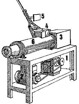
FIGURE 4.6.2-A Horizontal pug mill
with main parts named: gearbox (1), 3-HP motor (2), bearing house (3), feed
hopper (4), plunger (5), mixing barrel (6).
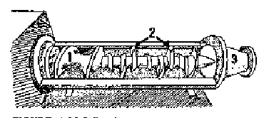
FIGURE 4.6.2-B Interior of pug mill
barrel with feed auger under hopper (1), mixing blades (2) and extrusion cone
mouth (3).
Common types of pug mills
Vertical pug mill
- drum type, non de-airing, side extrusion. This is a pug mill which uses a drum up to 60 cm in diameter for mixing clay. The earliest version of this mill used an animal to turn it, and the mill often consisted of a wooden box, which contained a wooden shaft mounted with a series of wooden blades (which sometimes had wires running between them to cut the clay). More modern versions are made from metal drums, and have a metal axle and blades which are powered by an electric motor. The speed of the pug mill is quite slow - about 8-15 r.p.m., and the speed reduction can be obtained by a combination of V-belts and pulleys, which are connected to an old automobile differential gearbox. The clay is extruded from a rectangular opening about 10 x 15 cm at the bottom. The limitation of these pug mills is that they can only extrude rather soft clay, and cannot be used for direct product extrusion, but the low cost and simplicity of the machine make it very popular for small producers.
The pug mill shown in Fig. 4.6.2-C is larger than usual, and is used mainly for mixing clay for insulating bricks (50 % by volume rice husks and sawdust), which normally needs to be quite soft. It can be filled with dry clay body mixture and water, unlike ordinary pug mills, which are usually fed with already plastic clay. It is equipped with a door on the extruder mouth, which is closed while the clay is mixing, and then opened to empty the mill. It has a 5-HP, 3-phase motor.
Vertical pug mill
- single shaft, non de-airing, bottom extrusion. This is also a simple kind of pug mill, and is capable of being made by a small producer. It consists of a cylinder and a series of blades which mix the clay and force it out of the end. It cannot practically be used for forming, because compression is too low.
Horizontal pug mill
- single shaft, non de-airing. This is as simple as the horizontal pug mill, but sits horizontally. It can be fitted with simple dies and a cutting table, for products like hollow bricks.
Horizontal pug mill
- single shaft, de-airing: Has a vacuum box which removes air from the clay. This requires a screen, which extrudes small “noodles” of clay into the vacuum box. After the air is removed, the clay is recompressed and extruded. This is used for producing high quality clay body, and can also be used for hollow bricks and split tiles. De-airing pug mills are rather sophisticated to construct, and should not be attempted by the inexperienced. Single shaft pug mills are a bit difficult to feed, because the clay tends to get stuck in the feeding mouth. Many of them are fitted with a metal roller, which helps force the clay into the blades, or with a plunger like the one shown in Fig. 4.6.2-A.
Horizontal pug mill
- double shaft, de-airing: This is the same as above, but in the first mixing chamber, it uses two shafts fitted with screw blades that turn toward each other. This makes feeding it easier, and it also mixes the clay better. The clay is compressed and extruded by a third shaft.
- Combined vertical drum mixer and horizontal extruder, non de-airing: This type of machine is widely used in small-scale tile and hollow brick industries. It uses a drum to thoroughly mix (already plastic) clay, and then feeds the clay into a horizontal extruder.
- Combined horizontal mixer and vertical pipe extruder,
de-airing: This is a mixer which feeds a vertical pug mill equipped with a die
for pipes. The machinery is heavy duty, because the clay for pipes must be quite
stiff.
4.6.3. TYPICAL
EXTRUDED PRODUCTS
Extrusion in recent years has gained more and more popularity, as it becomes very sophisticated. It probably finds its main use in the heavy clay industry, for production of hollow construction bricks and blocks, and for split tiles. While most of these products are too complicated for the small producer, there is good scope for the smaller and simpler types of hollow bricks.
Most small producers can benefit from the use of a simple hand extruder, which is a small investment that can quickly pay for itself in increased production of handles or decorative elements.
Clay for hand extruders should be prepared as for wheel throwing; i.e. thoroughly kneaded so there are no air bubbles. The clay is then formed into a cylinder slightly smaller than the extruder pipe, and placed in the pipe (which previously has been cleaned and fitted with the appropriate die). Clay is then extruded and cut to the needed length.
Extruded products
kiln shelf stands
Also called “posts”, these are easily made with a hand extruder (Fig. 4.6.3-A). Plans are given here for typical cross sections, and the construction of dies for hollow forms is shown.
A typical clay body for stands is fireclay with about 30 % fine grog (60 mesh and below).
The extruding step is quite easy - usually long pieces (30 to 45 cm) are made, but stands require accurate cutting and finishing so they are easy to use. Cutting is best done when the clay is softly leather-hard. First, the extrusion is straightened and trued by gently rolling it on a flat surface. A wire cutter can be used with a cutting box similar to a standard carpenter’s miser box. When enough stands of the same size have been made, they should be placed together vertically on a flat surface, and accurately sized by placing a flat wooden plank on top of them. This is beaten gently to make the stands exactly the same size. They then are ready for drying.
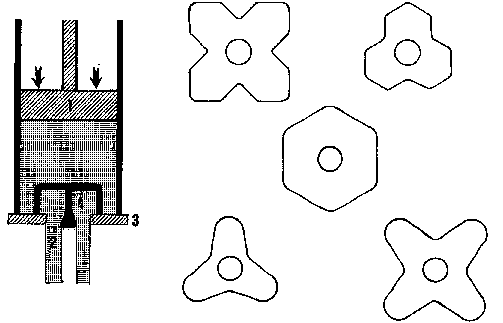
FIGURE 4.6.3-A Cross section of kiln
shelf stand with hollow extrusion die.
tiles
The most common type of tile made by extrusion is the split tile, which is made by special pug mill extruders that are capable of using very stiff clay. The tiles are extruded in pairs which are cut in two after firing.
Particle orientation and lamination_ produced by the auger action cause the tile to warp in drying or firing. This tendency can be reduced by striking the right balance between stiffness and plasticity of the clay body, auger speed and length of reducer and extrusion die. Sometimes wires are set inside the barrel after the last extruder blades in order to reduce lamination by cutting up the clay.
It is nearly impossible for the inexperienced potter to make his own tile extrusion dies. In industrialized countries this job is left to specialists who will tailor dies for the particular extruder and clay body used by the customer It is not recommended for the small producer to try to make his own extrusion dies for split tile making.
However, for small decorative tiles that do not need to be especially flat or exactly equal in size, the hand extruder can be used. The pug mill can be used for extruding clay slabs to be used for leather hard pressing, because the pressing breaks up the auger lamination by realigning the clay particles.
handles
One of the best uses of the hand extruder is for making handles. Lengths of clay are extruded, and then cut to the desired size (see chapter 4.4.1).
bricks
Bricks are made with a horizontal pug mill, or with a combined vertical drum pug mill with horizontal extruder. There are two systems - using soft clay and using stiff clay which require different machinery. De-airing is not normally used for common quality bricks made by small factories, although it certainly is necessary when special quality bricks (glazed bricks, for example) are desired. In large brick industries, where large and complicated bricks are made, very heavy duty de-airing extruders are used.
hollow bricks
When bricks are formed by extrusion they can be extruded hollow as shown in Fig. 4.6.3-C. This has the advantage of reducing the amount of clay used for each brick and thereby also reducing fuel cost. The bricks are still strong enough for normal construction and they are better heat insulators compared to solid bricks.
clay for hollow bricks
The clay used is fairly rough clay suitable for common bricks, but may need slightly higher plasticity. It normally is not washed, and in fact may often contain some roots and rocks. For this reason, if the pug mill extruder has a screen, it is generally removed so that it does not become blocked.
hollow bricks - soft clay system
Machinery for the soft clay system does not need to be heavy duty, so it is quite inexpensive. It produces a brick from clay the consistency of wheel-throwing clay, so it is feasible to fit a die on a standard pug mill. The main disadvantage is that the product is difficult to handle, so it requires large numbers of boards on which the wet bricks are placed for drying. The holes are normally made to run through the largest face of a standard size brick (as in Fig. 4.6.3-C), because this gives it the greatest strength when used in construction. Extruders with a small barrel can be made to extrude bricks with the holes running through the end faces (Fig. 4.6.3-D). These will be less strong but they are quite suitable for filling in walls in reinforced concrete constructions and for single storied houses.
hollow bricks - stiff clay system
The stiff clay system requires more expensive machinery, which must be strong enough to extrude almost leather-hard clay. The advantage is that the bricks are strong enough to handle immediately after extrusion, and can even be stacked for drying. It also permits easily making larger size bricks.
Extruding machinery can be powered either by an electric motor, where a 3-phase line of suitable capacity is available, or by a petrol or diesel engine. For a typical soft clay extruder, a 10-HP motor is required, and for the larger stiff clay extruder, up to a 30-HP motor.
Hollow bricks production need not be done in a factory, and the bricks are usually made during the dry season in monsoon countries. The only requirement is a simple shed roof to cover the machinery and motor. Kilns may be the periodic type, which may or may not be covered with a roof, or a continuous type of kiln is used (usually a “bull-ring” kiln). Standard brick kilns can be used for hollow bricks with no conversion. Another system for firing uses rice husks as fuel. Bricks are stacked inside a semipermanent kiln wall which is also made of hollow bricks, and gaps between the bricks are filled with rice husks. The “kiln” is left open at the top, and the fire is started from one side on the bottom. As the rice husks burn and settle, more rice husks are filled from the top. This type of firing may take several days.
pipe
Clay pipe has been used since ancient times for carrying both fresh water and sewage. It also is used as stovepipe for cooking stoves, and as perforated pipe for drainage and irrigation.
Ceramic pipe can be made with diameters up to about 1 meter. It usually is produced in lengths up to one meter, as longer pipes are difficult to dry and fire without bending.
Additionally, a variety of special shapes are made: bends (elbows), tees, siphons, etc.
FIGURE 4.6.3-E Hollow brick work
flow.(A; B; C)
A) Clay is stored in the open. If possible the brickwork is put
up next to the clay pit.
B) Clay is soaked with water into the pug mill
C) Clay is mixed in a U-mixer or a drum mixer.This normally feeds directly.
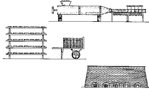
FIGURE 4.6.3-E Hollow brick work
flow.(D; E; F)
D) The premixed clay is extruded onto a cutting table from where the cut bricks are taken for drying.
E) Soft extruded bricks are initially dried on boards and as soon as they can be handled they are dried in normal stacks.
F) Hollow bricks are fired in ordinary brick kilns
parts of ceramic pipe
- Barrel: This means the main tube of the pipe.
- Flange:
This is the expanded end of the pipe, sometimes called the
“collar”.
- Socket: the inside of the flange
- Nipple: the small
end of the barrel, which fits inside the flange.
pipe forming and appropriate products
wheel throwing
This is generally used for relatively thin pipe for stove chimneys, or for short distance, low pressure water lines. Pipes made this way are relatively rough, but quite suitable for these uses and can easily be made by traditional potters as a new product. (Smokeless stoves are very popular in development work, and provide new sources of income for traditional potters). These pipes are generally 10 to 15 cm in diameter, and are easily made 60 cm long.
The process is to make the pipe in 2 pieces, each about 30 cm long, on the potter’s wheel. One piece is a straight pipe, and the other one is thrown with a flange on the top. The sections are joined when leather-hard.
These pipes are generally fired at low temperatures, using common clay and traditional firing systems. There is no reason, however, why they cannot be made from stoneware clay and glazed, where small quantities are required.
Average daily production: from 10 to 30 pieces.
slab construction on wooden moulds
This technique uses a wooden form shaped to the inside of the pipe. Slabs are prepared using any standard method (see slab construction, above) and then are wrapped around the form and joined. A special shaping device fits into the top of the form, and by rotating it around the slab, the flange is finished.
These pipes can be used in the same way as hand-thrown pipe. They have the advantage of being more uniform than wheel-thrown pipes.
Average daily production: about 30 pieces, by 2 persons.
slab construction in plaster moulds
This uses a two-piece mould made from plaster of parts, or clay/cement (see moulds below). Rather stiff clay is made into slabs, and cut into two long strips which are fitted into the two halves of the mould. The edges are trimmed so that they come slightly above the edges of the mould. Then they are coated with slip and scratched. The two halves of the mould are placed together and pressure is applied. Then the seam is pressed together from the inside, using a sponge and the hands. If the clay is stiff enough, the mould can immediately be placed upright so the pipe sits on its small end (not on the flange). The mould is carefully removed and can immediately be used again. This is quite a fast process for an experienced worker.
This process is suitable for straight pipes, and also is commonly used for special fittings, such as bends.
More complicated shapes such as tees, Y-connectors, junction boxes and reduction fittings are usually made by piecing together sections of straight pipes that have been cut to the appropriate contour.
Average daily production: about 30 pieces.
extrusion
The standard industrial process for making stoneware sewage pipe and water pipe is by extrusion. This is done with rather heavy machinery, and depends on fairly large production quantities to make it profitable (starting from a minimum of about 8 tonnes per day). Therefore it is recommended only if there are a sure market and sufficient supply of raw materials. Additionally, sewage pipe because of its low profit margin tends to be produced for a fairly local market, since transportation cost over long distances is not competitive.
Because pipe manufacturing on this scale requires a major investment and specialized equipment, it is recommended that first the process be studied in an existing factory. Additionally, machinery manufacturers should be consulted for their recommendations, bearing in mind that they have a vested interest. Before deciding to order machinery, the wise producer will first visit other factories using their machinery and discuss problems with the operator. It is also important to find out about servicing the machinery. If your factory is far from the equipment supplier, you should make sure that the machinery can be maintained and repaired by local mechanics.
pipe production hints
There are variations in the work flow, depending on what kind of clay, firing system, etc., are used. For example:
- different clays require different grinding machinery. A hard, nonplastic clay usually requires a pan grinder to break it down. For this kind of dry grinding, the type of pan grinder with a perforated pan works well, but a solid pan type may be a better choice, because it also can be used for wet or semi-dry mixing if necessary. For softer clays, a rotary hammer mill or pin mill of sufficient capacity will do a good job, as well as being cheaper.
- Screening: Since pipe clay is rather coarse, a rotary screen is sufficient for removing particles bigger than 16 mesh (standard insect screen can be used). This can easily be fabricated locally, is cheap and easy to maintain. Alternatively, a very simple vibrating screen can be used.
- An alternative to soaking the clay and then using a standard pug mill is to use a double shaft mixer (U-mixer), which mixes powdered clay body and water efficiently. However, a standard pug mill can be used for other purposes if desired - for example, for producing hollow bricks.
- The pipe extruding machine is really the only specialized machine required for this process. It is essentially a vertical extruder equipped with a die for the pipe barrel. It is equipped with a special die that first moves up under the extruder to form the pipe flange under pressure, then moves downward as the pipe barrel is extruded.
- A clutch system disengages the extruder while the pipe is cut or even just pulled off the machine. Then the flange die moves back into position under the extruder and another pipe is formed.
- The trimming and finishing machine is simply a rotating horizontal metal cylinder that fits the inside diameter of the pipe. A leather-hard pipe is pushed onto it, and then is cut to the correct length with a special knife tool, that also makes grooves at the end of the barrel for gripping the mortar better.
- Drying the pipes is normally done in the open air, with the pipes lying vertically on the floor. It is important to rotate them several times a day, as they will bend if they dry unevenly. Factories located in monsoon countries have difficulty with drying during the rainy season. If a continuous kiln is used, it can be built under a high roof so that the top of the kiln can be used as a hot floor dryer. More sophisticated drying systems are normally not used, as they increase the cost of the pipes too much.
- Grog: Pipe clay body normally contains about 10 % grog. This grog is obtained from pipe that is damaged in firing, which in a successfully running factory is normally about 10 %. The grog can be made in the same pan grinder used for grinding clay body.
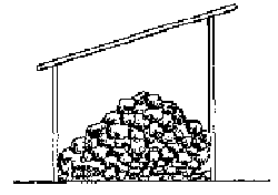
FIGURE 4.6.3-G Pipe extrusion work
flow.(A)
A) Clay is stored dried.
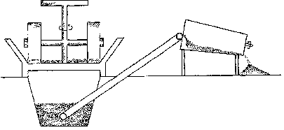
FIGURE 4.6.3-G Pipe extrusion work
flow.(B)
B) Clay and grog are mixed and crushed in a pan grinder and then screened
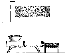
FIGURE 4.6.3-G Pipe extrusion work
flow.(C;D)
C) The screened pipe body is soaked with water.
D) The soaked
clay is premixed in a pug mill.
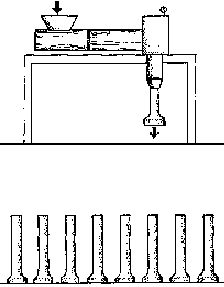
FIGURE 4.6.3-G Pipe extrusion work
flow.(E;F)
E) Combined horizontal pug mill with vertical extruder forms
pipes with flanges.
F) The extruded pipes are left to dry until leather-hard.
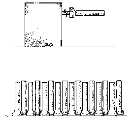
FIGURE 4.6.3-G Pipe extrusion work
flow.(G;H)
G) The leather-hard pipes are cut to size on a trimming
machine.
H) The pipes are left to dry in the open ,in a dryer or on top of
the kiln.
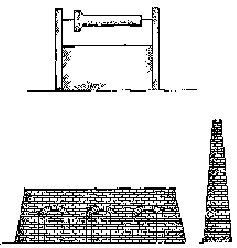
FIGURE 4.6.3-G Pipe extrusion work
flow.(I;J)
I) Before firing the pipes are glazed with a slip glaze.
J)
The pipes are fired to vitrification in special
kilns.
 |
 |
