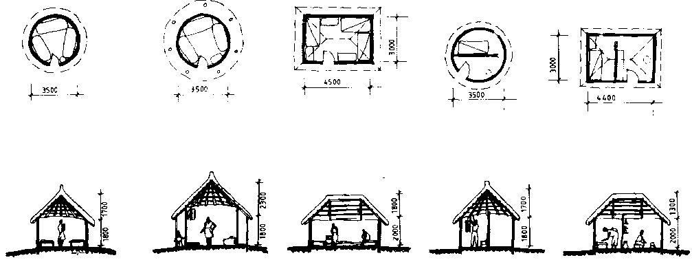
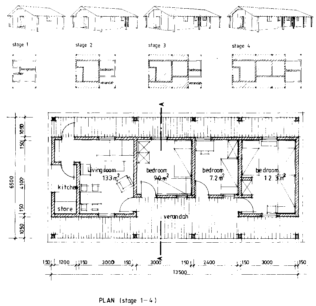
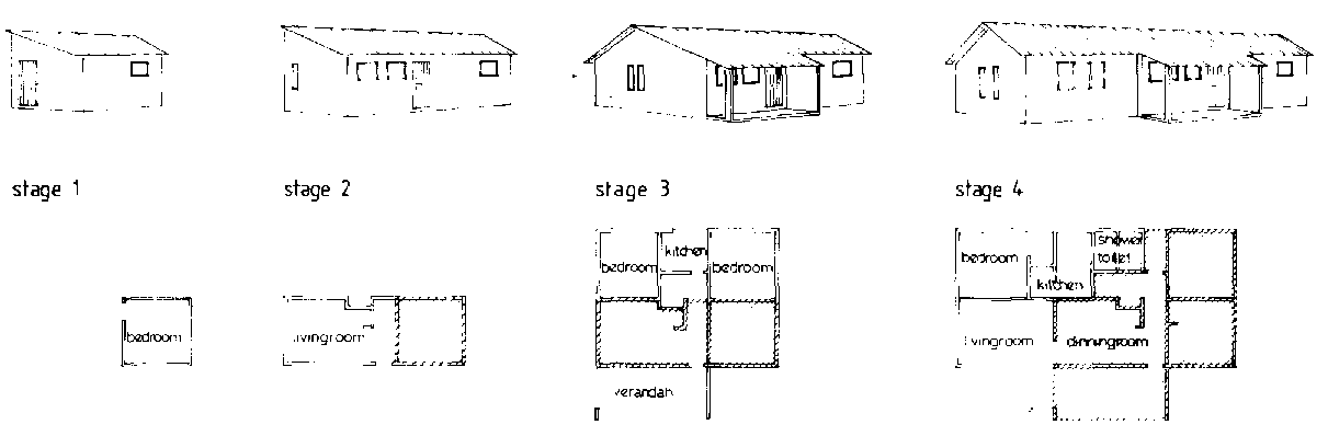
For the farm family that choses to use one of the expandable systems shown in Figures 12.23 and 12.24, a number of local materials are suitable. A foundation of stone or brick masonry or concrete is desirable, but then adobe blocks, mud and poles or stabilized soil blocks are suitable for the walls. While corrugated steel makes a clean, leakproof and durable roof, where it is available, thatch is less expensive and perfectly satisfactory. Thatch will require a roof slope of approximately 450 and the frame should be build high enough to allow the eaves to be a minimum of 2m above the ground. An overhang in the verandah areas will require support as shown in the figures.
When resources allow, the same designs shown in Figure 12.23 and 12.24 may be built with concrete foundations and floors, along with durable masonry walls of brick, concrete blocks and other available material. The temperature extremes typical of corrugated roofs can be reduced with the installation of insulated ceilings. The final result will be a secure, easily cleaned and durable home. Although considerably more expensive than dwellings made completely of local materials, this type of construction should be feasible for the emerging farmer who is producing some crops or animals for the commercial market.
Figure 12.22 Traditional homes for sleeping or sleeping and cooking.
Figure 12.24 Improved farm dwelling design, Ministry of Agriculture and Water Development, Zambia.
Andersen K.B., African Traditional Architecture, A Study of the Housing and Settlement Patterns of Rural Kenya, Nairobi, Oxford University Press, 1977.
Enzmann J., Farm Dwellings, Lusaka, Ministry of Agriculture and Water Development, 1984.
Kaszner O., Guidelines for Room Types in Low-cost Housing. with Reference to the Highland Climatic Region, Nairobi, Housing Research and Development Unit - University of Nairobi, 1977.
Neufert E., Architect's Data - Handbook of Building Types, 2nd edition., London, Granada Publishing Ltd., 1980.
Olesen F., Low-income House Types for Kenya, a Selection of House Types with Estimated Construction Cost Prices, Suitable for the Low-income Group, Nairobi, Housing Research and Development Unit - University of Nairobi, 1979.
Schreckenbach H., Abankwa J.G. K., Construction Technology for a Tropical Developing Country, Eschborn, German Agency for Technical Co-operation (GTZ), 1982.
Svard C., Rural Low-cost Houses. Advice Concerning Design and Choice of Materials for Rural Housing in Tanzania, Technical Pamphlet no. 3, Dar es Salaam, National Housing and Building Research Unit, 1980.
This chapter deals with rural structures which are only indirectly related to buildings, but which are of great importance to the farmer. These include roads, farmstead courts, minor river crossings, fencing and animal handling yards.
Rural access roads range from the simplest earth roads to bituminous surfaced highways. However, earth roads are normally the only type that can be justified for access to farmsteads. These roads, designated as unimproved earth roads, are generally suitable solely for light traffic, up to some dozen or so vehicles per day, and they often become impassable in the wet season. Heavy lorries, which sometimes need to have access to farmsteads, should only be allowed on this type of road after an adequately long dry spell. There is no need for actual structural design of unimproved roads, but there are some principles, which if followed, will produce a reasonably good road for the small investment that they justify.
Road Location
Some roads are built entirely new, but more often a sequence of communication routes evolves as the area develops. This may start with a footpath, which later turns into a track and, by gradual improvement becomes an earth road which is passable throughout most of the year. It is therefore advantageous to choose a road line at an early stage in the planning which will allow for gradual improvement of the road without having to make long and costly diversions.
A survey to determine the best location for a road line starts by identifying areas through which the road must pass, for example, a gap between hills, the best location for a river crossing, and points to be linked by the road. Places to be avoided include soft ground, steep slopes, and big rocks. In large scale road projects the terrain is viewed from aerial photographs, but for smaller projects this is too costly and instead an overview of the proposed road line must be obtained from adjacent hills. Such an overview provides valuable information on natural drainage, but should always be supplemented by a detailed examination on foot.
Once the points through which the road must pass have been established, the road line is laid out to run as directly as possible between them. When possible, roads should be located on sandy soils in well-drained locations, avoiding wet and low lying areas prone to flooding. To take full advantage of natural drainage, it is practical to locate the road along the backbone of a watershed if it roughly parallels the road line. By doing so, the best possible drainage away from the road will be achieved and expensive bridge, culvert or drift construction may be avoided. However, an attempt to avoid all the difficult spots may result in a longer road and the additional cost of the construction and maintenance should always be weighed against the cost for a road built in a more direct line.
Gradients
A steep gradient not only slows down traffic and limits the load a draught animal can pull, but it also complicates the road construction and increases the cost since care must be taken to avoid erosion from storm water flowing on and along the side of the road. A gradient can be expressed in three ways:
The recommended gradient standards for unimproved roads differ in different countries, but generally, for roads used mainly by motor vehicles, the gradient should not exceed 1 in 17 in flat or rolling terrain, 1 in 13 in hilly terrain, or 1 in 11 in mountainous terrain. In exceptional cases it may be necessary to have steeper gradients, but their maximum length should then be limited. In hilly terrain 1 in 11 can be allowed over a maximum of 500m and in mountainous terrain 1 in 9 over a maximum of 150m. Roads frequently used by draught animals should have a gradient not exceeding 1 in 20 or in exceptional cases a maximum of 1 in 10 over short distances. Pack animals can manage steeper gradients: 1 in 10 with a maximum of 1 in 8. The ability of lorries to ascend steep gradients in wet conditions will improve if the surface is gravelled, but that is expensive.
Curves
A straight road is the shortest distance between two points, but as noted earlier, this may not be the most economical line for a durable, easily constructed road which is passible throughout the year. Long gentle curves are preferred since there is better visibility and less speed reduction necessary than on a sharp corner. The minimum radius for a horizontal curve is 15m but 30m or more is preferable. Banked curves are seldom a consideration when building earth roads since the speeds are generally low. Sharp ridges which may diminish visibility or require cutting can almost always be avoided.
Slopes
Only occasionally will an unimproved road require embankments or cuttings, but where it cannot be avoided, the side slopes should not exceed 1 in 1 on well-drained soils. In wet soil it should not exceed 1 in 3, i.e. one unit rise in three units of horizontal distance.
These are maximum values and should only be used where the depth of the cut or fill is so large that to reduce the slope would be too expensive.
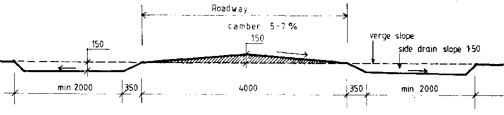
Camber
The camber is the slope of the road surface to the sides designed to shed water into the side drains. A simple earth track has no camber and no side drains. But all other roads should have a camber of 5 to 7% from the middle of the road, thus shedding water into both side drains. In deep cuts (where the road is dug into a hill side) or on sharp curves, the camber is designed to drain water from the whole surface inwards toward the cut or to the inside of the curve.
Cross Section of a Simple Earth Track
The simplest earth track is obtained by merely clearing vegetation and stones from the natural soil surface. It may run between fields within a farm, from the main road to a farmstead or between small villages where the traffic volume is very low. Earth tracks are based on single lane traffic in one pair of wheel tracks, but vegetation should have been cleared wide enough to allow for two small cars to meet. The road surface should be level with the surrounding terrain so that water can pass across it in any direction. If the tracks deepen, they should be filled in so that any water running down a slope will be able to pass across the road at any point, thus preventing water from accumulating in the tracks and causing erosion or lower bearing capacity. Where the road is running with a gradient, low gentle humps across the track will direct water flowing along the road into the surrounding terrain. In wet spots or in areas with high rainfall, it may be impossible to maintain the simple earth track in a passable condition. The cheapest way to increase the carrying capacity in such areas is to raise the level of the road and camber it as described in the next section.
Cross Section of an Upgraded Earth Road
These roads may be used to connect rural market centres and villages where the traffic volume is 10 to 20 vehicles per day including some heavy lorries in the dry season. Generally the only affordable surface material is the soil found on the line of the road or in its immediate surroundings. The bearing capacity of the road depends on the type of soil and the prevailing climatic conditions. The road is constructed by digging out soil from the sides and throwing it on the road until the cross section illustrated in Figure 13.2 is obtained. The 30cm difference in level between the road surface and the bottom of the side drains, combined with the camber of the road surface, will ensure a much drier roadway with higher carrying capacity than the simple earth track.
Wet spots soon turn into mud if the traffic is frequent, making the road impassable if wet weather continues. Gravelling reduces the risk of mud forming, but a 50 to 70mm layer of gravel may more than double the cost of the road. It is usually far cheaper to further raise the level of the roadway. Up to a point, depending on the type of soil, the higher it is raised, the drier it will be. Only if mud still tends to form in wet spots will gravelling be necessary and then only in those spots.
Figure 13.1 Cross section of a simple earth track.
Figure 13.2 Cross section of an upgraded earth road.
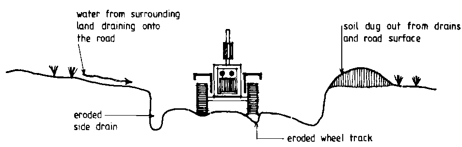
Figure 13.3 Road due to incorrect construction and maintenance.
Soil is eroded from a road by traffic, wind and water. Depending on soil conditions, climate and volume of traffic, soil erosion may cause considerable deterioration of the road and increase the cost of maintenance. While erosion from wind and traffic is normally of minor importance, that caused by run-off water from heavy rains can, if uncontrolled by proper drainage and maintenance, cause deterioration, beyond what is worth repairing in only a few years.
Properly installed drainage and road maintenance go hand in hand to insure the durability and carrying capacity of an earth road. If deep tracks are allowed to form, water will accumulate in them and since most roads have at least a slight gradient, the water begins to flow. As the volume of water increases either through intensity of rainfall or inadequate side drains, its speed and eroding action will increase. Side drains, if not properly installed, will also erode.
It is obvious then that drainage of earth roads is of primary importance. It is essential to remove rain water that falls on the road itself and to prevent that which falls on adjacent land from washing over the road. As far as possible natural drainage should be used to achieve these goals, but an engineered drainage system may be required to adequately protect the road. Rain water that falls on the road is shed from the curved surface (camber) into shallow side drains and diverted from there through mitre drains into the bush. Where necessary, catchwater drains should be constructed which collect water flowing towards the upper side of the road allowing it to be directed across the road and back into its natural channel in a controlled way.
Side Drains
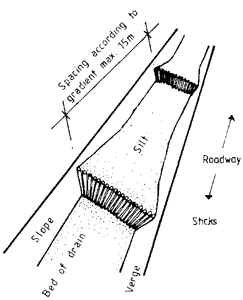
When side drains are dug, care should be taken to make them shallow but wide. Water in thin layers flows slowly without causing much erosion and the grass that will gradually grow in the drain will further slow the flow. Gradients not steeper than 1 to 250 are unlikely to cause erosion in ordinary soils. Where steeper grades are necessary, the drains should be emptied onto surrounding land at frequent intervals. Where a side drain has a very steep gradient, additional measures in the form of checks or gabions may be necessary. These checks will silt and form steps, thus decreasing the gradient and slowing the flow.
Figure 13.4 Scour checks will slow down the water flow in side drains with steep gradient.
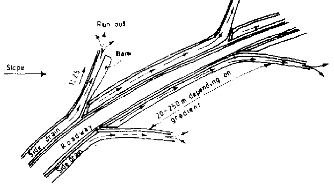
Mitre Drains
Mitre drains are used along high level roads to prevent build-up of water in the side drains. Depending on the gradient, mitre drains should be spaced 20 to 250m apart, using the closer intervals where rainfall is heavy, the soil is prone to erosion, or the gradient is steep. The mitre drain should block off the water flow in the side drain with a bolster block at an angle of about 30 degrees and lead the water well away from the road with a wide, shallow channel having a gradient of 1 in 125. The water is discharged 30 to 40m away from the road over as large an area of land as possible to prevent erosion. Figure 13.5 shows the use of mitre drains.
Diversion Banks
Simple earth roads having no side drains should have diversion banks at 30 to 250m intervals to divert water flowing along the tracks. Natural bumps in the road can sometimes be used as diversion banks if they can be improved to a suitable shape. These banks 30cm high and about 12m in length along the road should have a smooth contour allowing vehicles to pass easily at moderate speeds. The bank is connected to a mitre drain which feeds the water on to the adjacent land.
Catchwater Drains
Where a road is constructed along the lower part of a slope or cut into a hillside, a catchwater drain will divert the excessive flow of water down the hill and across the road line. Wherever possible, it should be constructed on the upper side of and at least 3m from the edge of the road and be separate from the side drain. This construction prevents the side drain from being overloaded with water from the slope. The water in the catchwater drain must be lead off across the road line back to its natural channel in a controlled manner. Wherever possible a natural waterway crossing the road should be used. If a controlled lead-off cannot be easily arranged, then it is better that no catchwater drain be used since water collected by it and flowing uncontrolled across the road will cause serious erosion and form gullies.
When the land has been surveyed and the most feasible road line has been found, the centre line of the road is set out with pegs inserted at 15 to 20m intervals and tall enough to be clearly visible. Additional pegs may be installed to mark the width of the roadway, side drains and the area to be cleared.
Stumping and Clearing
To construct a simple earth road, trees and rocks must be cleared from the road line and well back from the road so that sun and wind can dry the road surface. In heavily wooded country, trees should be cleared from the road way a distance equal to the height of the tree cover or even one and a half times that height on roads with north- south orientation. Wider clearing ensures visibility through bends and road safety in areas densely populated with wild animals.
Tree stumps can be removed by digging them out, burning them or by dragging them away with draught animals or a tractor. Rocks are either dug out and removed, buried, or broken down to ground level with a sledge hammer or by the hot-cold (fire-water) treatment. All holes are then filled and compacted and any bumps leveled. Stumps and rocks should be cleared well outside the roadway since the verges are likely to be used when vehicles meet. Any stones that cannot be removed and lie beside the roadway should be clearly and permanently marked with paint or a tall white peg. The final step in constructing a simple earth track is the building of diversion banks at suitable intervals.
If the objective is to construct a high-level earth road, the work will continue with the construction of side drains.
Construction of Side Drains
Using wooden pegs and string as a guideline, the edge of the road should be established 1.8 to 2.0m from the center line. On roads with no cross-fall, side drains are dug out of either side to a depth of 150mm and half the width of the roadway All soil thus dug out is thrown on to the road and spread to form an even road surface with correct camber.
It would be advantageous to excavate the side drains in several steps, allowing some traffic to pass on the road between each step, as some unevenness of the surface can be corrected in later steps when the high and low spots become visible.
The side drains are then shaped with a gentle slope of 1 :150 away from the road. The verge and back edge of the drain are shaped with a slope of about 3:1, thus avoiding the need for meeting bays, since vehicles can use the verge when meeting.
On sections of the road with steep cross-fall, the side drain on the upper side of the road is started at a depth of about 1 50mm and then dug slightly sloping away from the road into the hill. Where the cross-fall is steeper than 1 in 30, no drain is required on the lower side of the road and the road level and camber is then formed with material only from the upper side drain.
Mitre drains should be installed without delay, especially when working in wet areas. Boning rods may be used in uneven terrain to give the mitre drains an even gradient of 1 in 125. Later, on slopes where it is found necessary, catchwater drains may be installed to drain off surface water and divert it away from the road. Much of this water is often flowing down foot paths and cattle tracks and if small diversion banks are installed on these to divert the water into the bush well away from the road, the catchwater drain may become unnecessary.
Road Maintenance
The most important maintenance job on any type of earth road is to ensure that all drains work properly and that additional drains are installed wherever it becomes necessary. Secondly, rutted wheel tracks should be filled in with soil from outside the road bed. If the road surface becomes badly deteriorated it will be necessary to resurface the road by adding more soil from the side drains. Never remove earth from the road surface since this will lower the road level and make efficient drainage difficult or even impossible. Soil should be taken from the side drains so that they are made wider rather than deeper. On cross-falls, soil should be taken only from the upper side drain. During the first years after construction it may be necessary to control shoots from tree roots. When vehicles start using the road, bumps (other than diversion banks) and holes will soon become apparent. These holes and any other uneveness should be repaired promptly by filling.
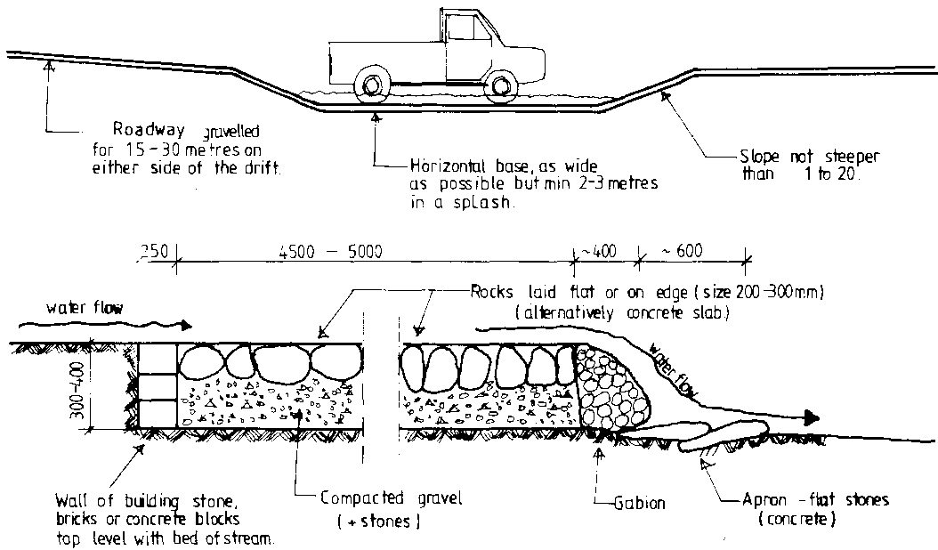
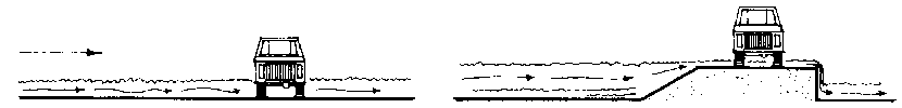
Where the road crosses a natural water way, a splash, drift, culvert or bridge should be built. Even if the waterway only carries water occasionally during the rainy season some kind of structure is necessary to keep the water that flows across the road from scouring and forming a gully. It is cheaper to build a splash or drift than a culvert. Bridge construction requires complex design calculations and is generally the most expensive alternative. The problem can often be simplified by choosing a road line closer to the watershed line or at an alternative crossing where conditions permit a splash or drift to be constructed rather than a more expensive structure.
Splashes and Drifts
Splashes and drifts are the same type of construction but their sizes differ. Splashes are associated with small local run-offs whereas drifts are built where a road crosses a stream or riverbed. Splashes are frequently used where water collected by a catch-water drain is directed across the road. Information given for drifts in the following paragraphs also applies to splashes.
A drift is best suited for a crossing where the river banks are relatively low and gently sloping and the stream is shallow. Concrete is the best material for surfacing the crossing, but in many cases is too expensive. Stone and gravel are used to surface most drifts, but if the flow of water is rapid the surface may soon be eroded. In some cases grass can be planted for stabilization or the flow can be slowed by widening the water course.
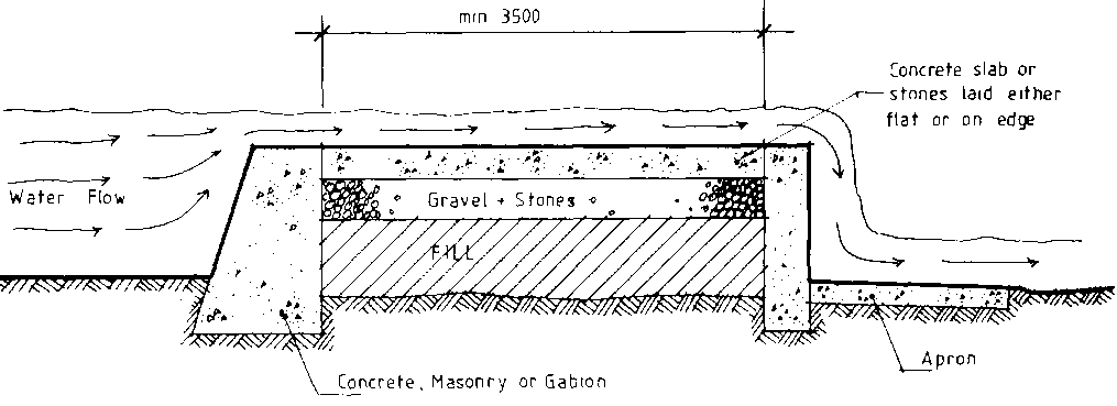
Figure 13.6 Sections of a splash or drift.
A drift should allow motor vehicles to pass at a reasonable speed during the dry season when there is little or no water. It should also be designed to allow traffic to pass during flood conditions, perhaps with the exception of a few hours or a day when the water flow reaches its highest level. However, such flows should not cause any major damage to the drift. For safety reasons a drift should be designed nearly perpendicular to the flow of water and the road approaching and crossing the drift should be straight for 20 to 30m on each side.
To maintain a uniform depth throughout its length, a drift must be constructed with a level roadway across the stream. While the dimensions of a drift are largely determined by the stream width and flow, a long level section will spread the flow and reduce the water depth and velocity to a minimum. For small splashes needing only a short level area, a minimum of 2 to 3m should still be allowed to avoid interfering with traffic flow during periods of no water.
The gradient of the road leading down to the drift should not be steeper than 1 in 20 and should preferably be gravelled for 1 5 to 20m on either side of the stream to avoid having mud form from the water that is carried up the slopes by passing vehicles. Where the road has to be cut into the river banks to decrease the gradient, run-off water on the road surface and in the side drains should be led away with diversion banks and mitre drains immediately before the road goes into the cut.
The edges of the drift must be stabilized with concrete blocks, big stones or gabions (stones wrapped in wire netting). The top edge on the upstream side of the drift should be laid level with the bed of the stream to prevent turbulence in the water flow and subsequent scouring and washing away of the road material. For the same reason the downstream edge should be level with the road surface and if a free fall is created, the river bed may be strengthened with an apron of flat stones to prevent undermiming.
Finally, the edges of the roadway should be clearly marked with stones or stakes which have been painted white. Depth markers are also desirable. They may be painted white up to the maximum safe depth and red above that to serve as a warning.
Embanked Drifts
Motor vehicles and other road traffic can tolerate shallow water better than deep water even if the flow is more rapid. In some cases the depth of water can be decreased by raising the roadway on an embankment. In streams with a low gradient (flat country) the water tends to bulk up in a deep, slow flow. An embankment drift with a free fall on the down-stream side will cause a rapid but shallow flow over the embankment. The increased water speed may, however, require the road surface to be concreted to avoid scouring. The edge of an embanked drift facing up-stream will normally have to be constructed in concrete or masonry work and be designed as a dam. The structure should preferably be carried down to a solid base in the bottom of the riverbed to avoid undermining.
Figure 13.7c Cross section of an embanked drift.
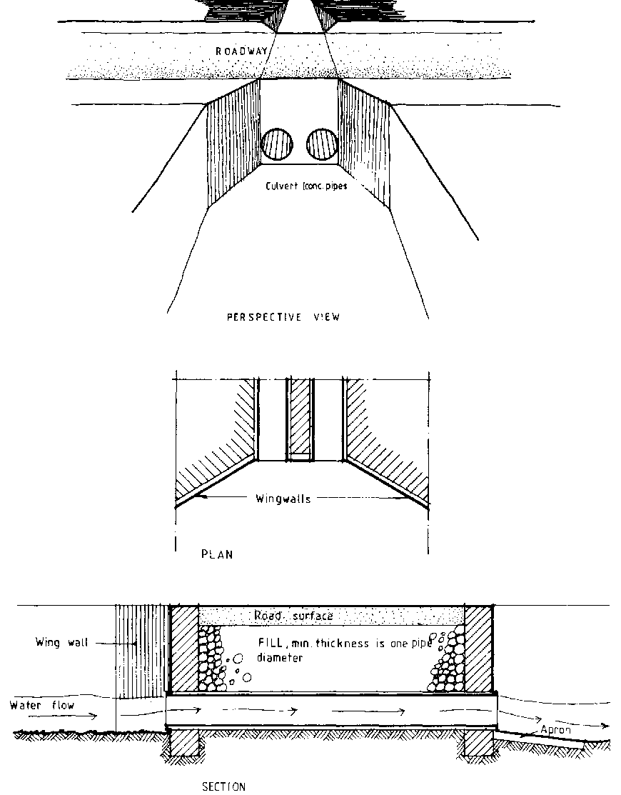
Culverts
Culverts are best suited for streams with steep banks, since their construction requires some difference in height between the level of the road surface and the bed of the stream. Culvert construction consists of the following:
Culverts may also be combined with embanked drifts. The normal water flow is carried by the culvert, but large flows of storm water are allowed to flow over the top of the embankment.
Concrete pipes, 400 to 900mm in diameter, are often used for culverts. The diameter and number of pipes is determined by the expected water flow. Alternatively corrugated steel pipes or masonry work in burnt bricks, concrete blocks or stone may form the culvert. Temporary structures may be constructed with logs, which are notched and fitted together. The bottom of the culvert should be laid on or slightly above the bed of the stream to avoid silting. Regular maintenance to clear the culvert of any silt or debris is essential.
Where concrete pipes have been used for a culvert, the embankment must provide for a soil cover above the pipe to a depth at least equal to the diameter of the pipe in order to sufficiently protect the pipes from the load of heavy vehicles. The beams in the ceiling of a square shaped culvert with masonry walls may be designed to carry the load of vehicles, thus reducing the need to spread the load in the embankment by a soil cover.
Many culvert installations have failed because the embankment has not been sufficiently protected by wing walls and have thus been washed away. In some cases the embankment can be built adequately strong with materials found at the site, but in most cases the extra protection of concrete work or a masonry wall is required. Water will tend to bulk up in front of the culvert and the height of the walls must allow for this. Wing walls, built with an angle, will guide the water flow into the culvert and reduce the bulking tendency. Since any culvert construction is likely to be overtopped by an extreme storm flow or because the pipe is blocked, provision should always be made for a controlled overflow through emergency spillways.
Simple Bridges
The ideal site for a bridge is where the river is narrow and the banks are solid. The bridge should be designed to interfere as little as possible with the natural flow of water. The highest level which the river is known to have reached is determined and the bridge designed to give at least 0.5m clearance above that level. A bridge includes the following:
Abutments, the structures provided to strengthen the stream banks and adequately support the shore end of the road-bearing beams. They can be constructed of concrete, masonry work (stone, brick, concrete blocks) or timber. The lower part of the abutments will normally require wing walls to protect them from the action of the stream.
Intermediate supports installed where the stream is too wide to be bridged in a single span. Timber trestles, masonry piers and reinforced concrete columns are the most common types of support. Intermediate supports must be designed to withstand the combined loads of the weight of the bridge and vehicles moving on it, plus the action of the flowing water and any debris floating in the water.
Road-bearing beams that carry the weight of the roadway and traffic between abutments and any intermediate supports. Simple bridges have road-bearing beams consisting of round or sawn timber or universal steel beams spaced about 600mm center-to-center across the roadway. For example, a bridge 3.0m wide requires 6 beams and a bridge 3.6m wide, 7 beams etc. The beams are usually designed as simple beams supported at the ends.
Decking or flooring, which make up the road surface on the bridge. Where poles or other rough materials have been used for decking a smoother surface can be obtained by putting planks along the bridge for the wheel tracks. The decking should be strong enough to spread the load from one wheel over at least two road-bearing beams. Wooden decking should never be covered with soil, since that will increase decay and disguise any weakness in the bridge.
Curbs made from poles or pieces of timber should be secured to the edges of the decking. Curbs will reduce the risk of vehicles slipping over the edge and will also, if positioned over the outer road-bearing beams and well secured to them, contribute to the strength of the bridge.
Rails along the edges of the bridge for safety.
The bridge must be designed to carry the weight of the members of the bridge (dead load) and the weight of any traffic moving across it (moving load). In order to simplify calculations, the moving load is often converted to an equivalent live load by multiplying it by 2. When a heavy lorry moves across the bridge, the bridge will carry concentrated loads from the wheels with spacings equal to the wheelbase and tread-width. In a bridge of short span the largest bending moment in the road-bearing beams will occur when the back wheels which carry the greatest weight are at the centre of the span and will be determined by half the weight on one wheel, since the decking is designed to distribute the load to at least two beams. In a bridge of longer span where both front and rear wheels may be on the span at the same time, the maximum bending moment will occur when the centre of the wheel base is a short distance from the centre of the span. In addition to bending, shear may have to be considered in short spans, and deflection for long spans. Where bridges are constructed with rough materials under unfavourable conditions a larger factor of safety should be used.